Mission-Critical Applications Require High-Voltage Capacitors to Meet Stability and Durability Requirements
Find a downloadable version of this story in pdf format at the end of the story.
In any industry, there are applications whose failure could mean lost revenue and increased annoyance. In very few industries, application failure could result in breaches in national security or even fatalities. In such markets, the design of mission-critical applications demands the utmost care and forethought. The military and aerospace fields are two areas in which reconstituted mica paper capacitors are used for numerous critical applications. These include aerospace ignition systems, baggage x-ray systems, power supply filtering for military and commercial applications, energy storage with high current discharges for military and commercial detonation systems, voltage multipliers, traveling wave tubes, radar, particle accelerators, power utilities, exciters for industrial generators, down hole well logging, partial discharge detection and welding equipment. The failure of any of these applications could be devastating financially, militarily or fatally, and is therefore unacceptable.
Reconstituted mica paper capacitors (RMPCs) shown in Fig. 1 are more stable than ceramics or most film capacitors and offer a durable platform from which to work when a high-voltage capacitor is required. RMPCs have a -3 percent max drift at -65°C from nominal capacitance reading to +5 percent maximum drift at 175°C and a temperature coefficient of less than ±500 ppm/°C for -65°C to 125°C operating range. Among the other unique benefits of RMPCs are the fact that these capacitors are not position-sensitive, nor do they have a polarity, although the outside foil can be identified for those that find it necessary. Additionally, RMPCs are solid state and contain no liquid to contaminate the electronic device or its surroundings, enabling them to tolerate physical shock and vibration.
Tests have shown that these capacitors can survive 100,000 Gs of acceleration. They can be subjected to a simple harmonic motion with amplitude of 0.06 inches and with a variable frequency from 10 to 55 Hz in each of three mutually perpendicular directions for two hours without damage. Thermal cycling and thermal shock from -65°C to 125°C will likewise cause no damage. Capacitance can range from 50 pF to 5 µF with voltage ratings from 1 kVdc to 75 kVdc and more with special designs. AC voltages up to 20 kV present no problem and can also be found with corona-free (no partial discharge) ratings. Peak current is usually limited by the inductance of the discharge circuit and not by the rise time effects of the dielectric. The mica used in RMPC is naturally resistant to radiation with an approximate loss of voltage/charge of absorbed dose at 0.12 percent krad. RMPCs are also a well-tested option. For example, there are satellite and space applications in which some RMPCs have been in continuous use for more than 34 years.
Design Considerations
Design engineers must keep in mind two operations when considering the testing and design of any high-voltage capacitors. These two operations should be viewed as two separate, but intertwined concepts with absolute reliability as the goal for both. In other words, testing cannot transform a capacitor that has been designed outside safe design limits into a reliable one, and a well-designed capacitor inadequately tested is equally undependable. When it comes to RMPCs and their related engineering and design functions, the involvement of a recognized quality management system is essential. Aerospace Standard AS 9100 is the ultimate quality management system (QMS) for the aerospace industry, as well as ISO 9000:2008. Both provide excellent business models for effective and efficient control of a manufacturing system.
Keep in mind that the voltage stress levels are different for AC and DC operations and are also subject to the temperatures at which they are tested. Corona inception and extinction levels should be determined as volts per mil stress at this stage, as well. Other areas that need to be defined are dissipation factor, IR, ESR, temperature coefficient and drift between the rated temperature extremes. Not any change of the components or processes used to manufacture the capacitors would require another set of testing-to-failure data.
Continue to next page
One should employ accelerated life testing and destructive testing or testing to failure in order to further delineate the operation design limitations. There are many software packages available that can predict life and confidence levels using the results from the accelerated life testing. Results will determine the maximum operating volt per mil stress of the dielectric and the maximum operating temperature that it can withstand, delivering a given confidence level that it will survive for the required length of time. Testing at critical points, such as after winding, impregnation and section assembly, weeds out early failures due to material defects or operator errors. The number of failures at these test points should be small; less than 5 percent. In lots where failures exceed this percentage, an investigation needs to be initiated to determine the root cause and if the lot meets the design requirements. Final testing establishes that the design requirements have been met, that the production processes are under control, and that any infant mortalities have been weeded out. The goal of these practices is to safely design the smallest and most reliable capacitor for the application. Using this method builds the desired life and characteristics into the device.
Meeting Designers’ Needs
At this point, after determining the safe operating design parameters, you can begin to address the end user’s specifications. First, one must maintain the specified size. Then the following questions need to be answered affirmatively:
1. Will the capacitor design accept the desired electrical charge safely? If the device successfully passes the dielectric withstand voltage, the answer is “yes.”
2. Will it hold the desired charge for the required amount of time with an adequate margin of time? If it passes the burn-in testing, we can again answer “yes.” Note that burn-in testing voltage is usually calculated as midway between the rated voltage and the dielectric withstand voltage and is applied at the highest rated temperature for 24 to 48 hours (more for the most critical applications).
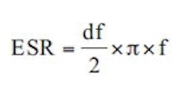
3. Will the current applied cause internal heating, and if so, how much and how will it be handled? The Irms and duty rate need to be specified by the customer or a current waveform supplied to the designer to determine the Irms. Self-heating can be calculated from its equivalent series resistance of the capacitor, which is directly related to its dissipation factor; typically 0.3 percent. The formula for equivalent series resistance is
df = Dissipation factor
f = Frequency
c = Capacitance.
One needs to take steps to ensure that self-heating will not raise the capacitor over its rated maximum temperature. Forced air circulation, oil bath or heat sinks are all means to reduce the temperature.
4. Will the capacitor be in operation with partial discharges/corona? While reconstituted mica paper is naturally resistant to the effects of partial discharges, it should be avoided, if possible. Corona-free operation offers extremely long life for the capacitor as noted by the example of the space application.
Temperature Extremes
Other problems associated with these specialized applications are that the design requirements can be at extremes. Life can be as short as a one-pulse discharge for munitions systems to >100 X 108 pulses for aircraft ignition systems. Voltage can range from 1 kVdc to more than 100 kVdc with an unending variety of waveforms that need to be studied for their effects in the circuit. Temperatures can range from the severe cold of outer space to the intense temperatures encountered in deep-well logging. Other design criteria that need to be considered are atmospheric pressures, thermal shocks/cycles, physical shock/vibrations and radiation. There might be other customer requirements that need to be met such as peak current, RMS current, inductance, impedance, ESR, humidity, special terminals, operating at reduced pressures, sheds or corona shields. These are the major concerns that need to be addressed early on. Some compromises by the end user may be needed, either allowing more room or reducing voltages/stresses so that they fall within allowable limits as defined by the destructive testing.
Continue to next page
The user usually specifies the capacitor packaging based on their application. If the capacitor is to be left exposed to atmospheric conditions, then a range of options are available. Tape-wrapped and end-filled, fiberglass/plastic/metal potting form or epoxy molded units (Fig. 2.) offer varying levels of environmental protection, structural strength and mounting options. If the final application entails potting the capacitor into an assembly, then a bare section design offers the best economy and smallest size. The choice of potting or casting materials whether epoxy, silicone, polyurethane or some other polymer, needs to be appropriate for the capacitor’s end use. The glass transition temperature, rated temperatures, Shore hardness, dielectric strength, volume and surface resistance, water absorption, shrinkage and thermal conductivity are some of the criteria that need to be addressed. The design of mold or potting forms should avoid sharp edges, sharp points or projections and allow for adequate coating of the capacitor pack. Fiberglass cloth may be used to wrap the capacitor pack to remove sharp edges and add structural strength in some applications. Some materials require that they be transferred to the mold under vacuum for best effects, and most require a heat cure for optimum performance
The typical dielectric stress voltage is 200 percent of the rated voltage up to voltage ratings of 8 kVdc, at which point the stress is reduced linearly to 110 percent at >45 kVdc. Capacitance is again checked after soldering, assembly and burn-in operations. Capacitance, df, and dielectric stress are once more 100 percent tested at the completion of packaging options. Other customer-specified testing might include, but is not limited to: burn-in voltage/temperature and length of time, corona inception and extinction voltages, capacitance, df, ESR, IR at various temperatures, thermo cycling/shock, shock and vibration, moisture resistance, fungus resistance, solderability, x-ray and resistance to various chemical. At a minimum, all capacitors should be tested 100 percent for capacitance, dissipation factor and dielectric stress at the bare single element stage to ensure that all the infant mortalities have been weeded out.
Designs of 1300 V/mil are the industry standard for the dielectric stress between foils associated with reconstituted mica paper capacitors with 26 V/mil for the margin area. These stress levels will meet the requirements for 100,000 + hours of reliable use. Different winding techniques such as straight winding with embedded foil, series winding with embedded foil and extended foil can be used to maximize desire characteristics. The number and location of tabs (terminals) are calculated to obtain the best current, voltage and induction performance. Many times, capacitor requirements are such that multiple capacitors must be connected in parallel, series, or a combination of parallel/series connections to achieve the desired capacitance/voltage rating.
RMPCs
Besides all the internal options available to users of RMPCs, designers can also choose various shapes for these capacitors (see Fig. 3.). The user must maintain the required volume for the capacitance and voltage rating, needed, but otherwise, the user is free to define the physical dimensions to fit their needs. For example, if a capacitor required 1 in. x 1 in. x 6 in. for a specified capacitance and voltage rating, it can be also be designed with almost any variation of dimensions that contribute to a final form measuring 6 cubic inches.
Download the story in pdf format here.
About the Author
Comment About the Article
To join the conversation, and become an exclusive member of Electronic Design, create an account today!

Leaders relevant to this article: