Don’t Assume Top LDO, Switcher Attributes Always Apply
Download this article in PDF format.
Every design begins with some assumptions, because you have to start somewhere. But as the design moves along, it’s often important and necessary to double-check if those assumptions are actually valid for the specific case. When a design needs a small dc-dc converter, the choices are between the low-dropout (LDO) and switching topologies. Each has differing characteristics and attributes, but each also has a “tag” with which it’s closely associated.
For LDOs, the word is that they’re inefficient; for switchers, it is that they’re noisy. While these are true of each in general, certain situations arise in which they may not be true or relevant in a particular configuration.
Assumption #1: “LDOs are less efficient than switchers”
In general, yes. A typical LDO’s efficiency is in the 60% to 80% range, while a switcher is likely in the 75% to 95% range. But these basic numbers are only part of the story. What efficiency do you need, and what are you willing to pay for it? Also, depending on the dropout differential between VIN and VOUT, the LDO’s efficiency may be at the high end. This is the often the case in battery-powered applications, where the dropout voltage may be small until the battery reaches its discharge knee and drops below a viable operating value.
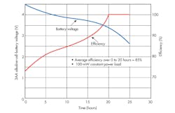
1. Perhaps it’s counterintuitive, but efficiency increases as battery voltage declines for this three-cell LDO design (100-mW constant-power load). Average efficiency near dropout is 85%, while at dropout, the battery has 20% capacity remaining, for a total cumulative efficiency of 68%. (Source: Maxim Integrated)
Or consider this scenario: When an LDO is operating from a battery, the initial input voltage is at a maximum and thus efficiency is low. However, it actually increases as the battery voltage drops (Fig. 1), which is not an intuitive trend. This efficiency trajectory is the opposite of what is typical for switch-mode regulators. Thus, it’s important to determine what the efficiency level will be for most of the battery's life, and the effect this curve has on battery life. The lower efficiency may only be the case for a short or modest period; therefore, its impact on battery life and run time may not be significant.
Also note that overall efficiency is a function of system duty cycle. Many LDOs are available with a shutdown control; when invoked, the quiescent current drops into the microamp range and losses are near zero. If the LDO is turned off for a significant part of the system’s operating cycle, actual efficiency integrated over a longer period can be quite high, even if active-mode efficiency isn’t as high as it is for a switching regulator.
Conclusion: Yes, LDOS are less efficient than switchers at first look, but “your mileage may vary”—and the difference may be minor in a specific application (Reference 1 offers additional insight into LDO efficiency analysis).
Assumption #2: “Switchers are noisier than LDOs”
Again, true in general. The generation of switching noise (EMI/RFI) is an inherent consequence of the operation of this topology, at a frequency that can range from a few hundred kilohertz up to several megahertz (it’s a function of the clock). Nonetheless, the first question to answer is “How much noise can I accept?” or its equivalent “How low does my noise really have to be?” If the amount of noise that can be tolerated is modest, a standard switcher may be acceptable.
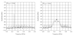
2. The output noise spectrum of the LTC3543 with spread spectrum disabled shows spikes at the clock fundamental and harmonic frequencies (left). With spread spectrum enabled, the fundamental and harmonic components are greatly reduced and the energy output is flattened across the spectrum (right). (Source: Linear Technology Corp.)
Even if that noise isn’t low enough, designers of switching regulators have employed a few tricks to lessen its impact and even reduce it. The noise impact is diminished by using spread-spectrum clocking, where the switcher’s clock isn’t at a fixed frequency, but instead is randomly “dithered” over a defined range.2 While this doesn’t reduce the total noise energy, it does attenuate its peak over the entire spectrum. Thus, instead of a noise spike at the clock frequency and smaller spikes at its harmonics, the noise spectrum is flatter with reduced peaks. This may reduce the noise to a level where it’s no longer a system concern, and even help keep radiated noise below regulatory thresholds.
This approach is used in Linear Technology’s LTC3543, a 600-mA synchronous step-down regulator. It has a nominal internal clock of 2.25 MHz, but can also synchronize to an external clock between 1 and 3 MHz, to better manage clock interaction. Figure 2 shows the reduction across the spectrum of the fundamental and harmonic achieved using the spread-spectrum technique.
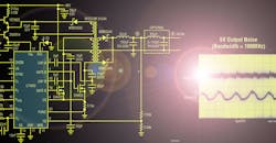
Also, designers of switching regulators have added clever, subtle “tricks” to the IC that reduce noise generation. For example, the LT1683 dc-dc controller from Linear Tech controls the voltage and current slew rates of the external N-channel MOSFET switches. These rates can be set independently to balance harmonic content of the switching waveforms vs. efficiency. The IC uses a push-pull current-mode architecture that’s optimized for low-noise performance. The combination of improvements can reduce high-frequency harmonic power by as much as 40 dB with only minor losses in efficiency (Fig. 3).
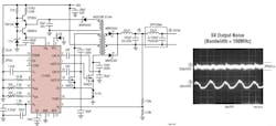
3. The schematic of the LT1683 switching-regulator circuit shows an optional output filter (left). With a 5-V output, switching noise is a little over 25 mV p-p before the filter and drops to just 200 µV p-p after the filter, a difference of over two orders of magnitude (right). (Source: Linear Technology Corp.)
Conclusion
The lesson is clear: Well-known LDO and switching regulator assumptions are generally true, but there may be exceptions in specific cases. That’s why it makes sense to step back and reexamine these assumptions. They may be making your design challenge more difficult or even drive it in a direction that isn’t necessary, potentially leading to adverse consequences.
References
1. Maxim Integrated, Tutorial 751, “Linear Regulators in Portable Applications”
2. Linear Technology Corp., “Easy-to-Use Spread Spectrum Clock Generator Reduces EMI and More”

About the Author

Bill Schweber
Contributing Editor
Bill Schweber is an electronics engineer who has written three textbooks on electronic communications systems, as well as hundreds of technical articles, opinion columns, and product features. In past roles, he worked as a technical website manager for multiple topic-specific sites for EE Times, as well as both the Executive Editor and Analog Editor at EDN.
At Analog Devices Inc., Bill was in marketing communications (public relations). As a result, he has been on both sides of the technical PR function, presenting company products, stories, and messages to the media and also as the recipient of these.
Prior to the MarCom role at Analog, Bill was associate editor of their respected technical journal and worked in their product marketing and applications engineering groups. Before those roles, he was at Instron Corp., doing hands-on analog- and power-circuit design and systems integration for materials-testing machine controls.
Bill has an MSEE (Univ. of Mass) and BSEE (Columbia Univ.), is a Registered Professional Engineer, and holds an Advanced Class amateur radio license. He has also planned, written, and presented online courses on a variety of engineering topics, including MOSFET basics, ADC selection, and driving LEDs.
Comment About the Article
To join the conversation, and become an exclusive member of Electronic Design, create an account today!

Leaders relevant to this article: