Thermal-Management Strategies for PCBs
What you’ll learn:
- Basic strategies to tamp down the heat in a PCB.
- Different parameters to consider while designing the board.
The race to make electronics smaller and more powerful has become a bit of a challenge when dealing with heat management in printed-circuit-board (PCB) design. Poor thermal design could shorten component life, degrade performance, and even cause catastrophic failures. Cooling techniques can be used to address the problem, but everything starts with the PCB design.
Every component that consumes power generates heat. This heat must flow from the component junction where it’s produced to the ambient air where it’s released. The efficiency of this heat path determines how hot it gets for your board.
Two primary forms of heat transfer are conduction and convection. Conduction would happen through the copper of your PCB and convection to the air.
The critical formula for designers: Tj = Ta + (P × θJA), where Tj is junction temperature, Ta is ambient temperature, P is power dissipation, and θJA is junction-to-ambient thermal resistance.
The datasheet becomes a critical source of information for the junction and the junction-to-ambient thermal resistance. Certain components, such as linear voltage regulators, require extra care in your design approach because they’re more prone to excessive heat generation.
Running any electronic component at its thermal limits may accelerate aging and, eventually, lead to failures in the hardware. Such failure can cause components like capacitors to burn out and result in a short, processors to run at reduced clock rates, or linear regulators to fail under load.
There’s a third form of heat transfer: radiation. Though it contributes to the overall heat transfer, its impact remains minimal in standard design and impactful in certain conditions, such as with specialized coatings or very high heat dissipation.
Proven Strategies for PCB Heat Management
Below are some of the strategies for addressing thermal management from a PCB perspective.
Optimize Copper Planes
Copper is an excellent thermal conductor. Large ground or power planes helps spread heat evenly across the PCB. Increasing copper thickness from 1 oz. to 2 oz. can reduce local temperatures significantly, especially in high-current PCBs. Keep in mind that these changes may affect the price of the PCB. Materials other than the standard FR4 could be considered to assist with better heat transfer.
Use Thermal Vias
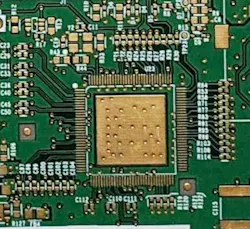
Thermal via arrays can be placed under heat-generating components like MOSFETs, voltage regulators, and integrated circuits (Fig. 1). The vias conduct heat vertically to other copper layers in the PCB.
Smart Component Placement
Position components where they best dissipate heat. This may be where airflow is maximized or where copper could be used to conduct heat so that it can be dissipated. Keeping hot devices away from temperature-sensitive parts like sensors will improve overall system reliability. Multi-layer PCBs can be used to distribute heat across the board. And assembly processes such as conformal coating could reduce heat dissipation in some cases.
Improve Airflow
Design your board to encourage natural convection. If needed, integrate fans, blowers, or heatsinks for forced convection. For sealed enclosures, use thermal pads or connect heat paths to a metal chassis or plate.
Heatsinks and Active Cooling
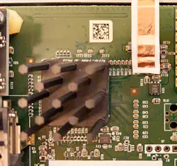
The use of external PCB mounted thermal heatsinks can keep systems from overheating (Fig. 2). Thermally conductive tape could also be used to transfer heat independent of the PCB.
Manufacturing and PCB Thermal Issues
Manufacturing defects may significantly impact a PCB’s ability to handle thermal issues. Any cold solder joints or loosely placed connectors can increase resistance in the current path and thus increase the amount of heat that needs to be dissipated. These problems can easily be addressed by optical or X-ray inspection. Artificial intelligence (AI) is also being used to aid inspection of PCBs.
A good PCB thermal design will ensure consistent operation and long-term reliability.
About the Author

Amit Arvind Nene
Senior Electrical Architect, Collaborative Robotics
Amit Arvind Nene is a Senior Electrical Architect at Cobot - Collaborative Robotics Inc. He specializes in hardware architectures for computer vision and artificial intelligence applications. Previously, Amit held the position of Senior Electrical Engineer at Grabango, focusing on high-resolution camera design and advanced system-on-module (SoM) and system-on-chip (SoC) solutions.
Amit holds a Master's degree in Electrical Engineering from Missouri University of Science and Technology and a Bachelor’s degree in Electronics and Telecommunication from Maharashtra Institute of Technology.
Comment About the Article
To join the conversation, and become an exclusive member of Electronic Design, create an account today!

Leaders relevant to this article: