Novel Electronics Cooling Solution Improves Power Handling of Small Packages
K-Core thermal spreader cold plates provide high-efficiency heat transfer in the absence of moving parts and are invaluable in applications where space, volume, seamless hardware integration and weight constraints dictate thermal design solutions. In this work1, trade studies involving different heat exchanger/cold plate materials as well as various fault scenarios within a typical electronic system are investigated to illustrate the upper bounds placed on the convective heat transfer coefficient.
Physically, k-Core-based thermal spreader cold plates absorb heat from sources such as high-power dissipating electronic components, rejecting it to ambient air or liquid coolants. These types of cold plates are well suited for operating in harsh environments. For cooling high-power density applications (e.g., semiconductors, lasers, power generation, medical equipment, transportation, military electronics, etc.) and other demanding applications where air cooling is insufficient, liquid cooling is essential. In this work, the heat transfer of k-Core thermal conduction plates available from Thermacore Inc.2 is studied in conjunction with a pumped fluid loop.
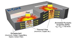
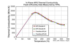
Figure 1 illustrates the physical concept of Thermacore’s k-Core heat transfer technology. Using encapsulated Annealed Pyrolytic Graphite (APG) allows you to manufacture a device such as a heat spreader with heat sink integrated on one face while a labyrinth of tubing for a pumped fluid loop can be fabricated on the opposing face. Since APG is anisotropic in thermal conductivity, with the x- and y-components of thermal conductivity being very large with respect to the z-component, the APG heat sink/heat spreader greatly enhances overall heat transfer via preferential heat spreading. Figure 2 shows the temperature dependency of the thermal conductivity of APG.
System Description
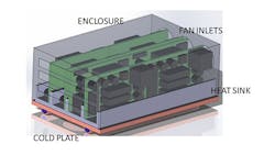
The configuration of Figure 3 represents a medium-sized high-power density electronics application. The overall system consists of a very large housing with eight identical sub-modules arranged in order to minimize overall system volume. The sub-modules were each populated with various components, totaling twelve each per sub-module. The thermal control system has three major components: the heat sink, the cold plate and the forced convection fans/housing enclosure. The enclosure is roughly the size of a footlocker (W × L × H = 0.5 m × 1.0 m × 0.5 m).
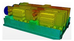
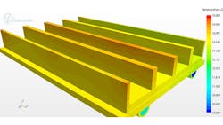
The mesh for the simulations with STAR-CCM+ consisted of a polyhedral unstructured mesh with five prismatic layers to resolve the boundary layer at all solid-fluid interfaces (Fig. 4).
Typical cell count for the system-level CFD model was on the order of 2.5 million cells; the particular mesh size was selected from runs to determine the optimum mesh size giving accurate answers as quickly as possible. CPU run-time on a 64-bit quad-core workstation was on the order of six hours.
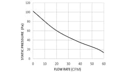
The simulations included fully 3D conjugate heat transfer, forced external air convection, forced internal liquid cooling loop, solid conduction, and surface-to-surface gray body radiation. To mimic typical Commercial Off-The-Shelf (COTS) cooling fans, the fan curve (for a fan rated at 30 CFM with 50 Pa static pressure) of Figure 5 was used in the simulations.
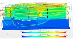
The baseline simulation results showing temperature distribution and streamlines are illustrated in Figure 6. The parameters for each of the hardware subcomponents in the simulation were set up so the power density at the liquid cold plate is 1.6 kW/m2, which is in the category of a very high-power density application. Once the baseline results were obtained, trade studies were performed to determine system sensitivities.
Heat Transfer
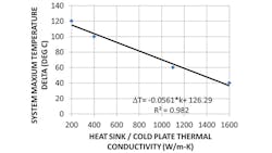
The primary objective of this work is to demonstrate the heat spreading characteristics of APG k-Core material in comparison to traditional heat sink materials. To accomplish this, the thermal conductivity of the heat sink/cold plate was varied from a very low (bare aluminum) to a very high value (APG k-Core). The results of this parametric study are shown in Figure 7 showing the expected linear variation of the system temperature as a function of the heat sink/cold plate thermal conductivity.
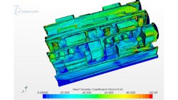
The thermal performance of a system will significantly vary with the flow rate provided by the fan and a key way to measure the variance is with the convective heat transfer coefficient. Figure 8 shows values of convective heat transfer coefficient for a typical CFD simulation. These were in agreement with the heat-transfer literature3 for systems of this category.
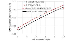
To quantify the effect of inlet-fan air speed on the heat-transfer coefficient, a series of simulations was performed with varying flow rates of air, resulting in a different average velocity emanating from the fan. Figure 9 shows the results of the simulations compared with Ellison4.
The correlation of Ellison is conservative, as expected, and corresponds to standard textbook-based correlations with typical uncertainties of at least 25%. The data from our CFD study are also found to be in qualitative agreement with the simulations and correlations offered by the research published in “CFD Analyses of a Notebook Computer Thermal Management System and a Proposed Passive Cooling Alternative”5 and “A CFD Based Analysis on the Effect of Free Stream Cooling on the Performance of Micro Processor Heat Sinks.”6.
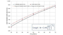
Next, the heat-transfer coefficient of the system is plotted against temperature delta of the system as shown in Figure 10. The CFD data points are assigned a power-law curve fit and compared to the correlation offered by Y. A. Cengel in “Heat Transfer—A Practical Approach.”7
The handbook correlation is found to once again over-predict the heat-transfer coefficient. As mentioned above, the heat-transfer correlations are expected to carry an uncertainty of at least 25%. The agreement of the CFD results in Figures 9 and 10 are within the realm of this uncertainty range.
Coolant Flow Rate
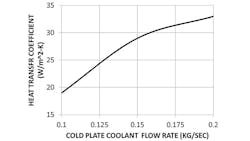
Next, a series of CFD simulations was carried out varying the inlet flow rate of the water in the cold plate. The heat-transfer coefficient of the entire system is plotted as a function of the flow rate in Figure 11.
As can be seen in Figure 12, the heat exchanger/cold plate assembly maintains a relatively constant temperature. This is the primary advantage of utilizing a pumped fluid cold plate apparatus, i.e., it gives one the ability to hold a nearly isothermal boundary condition in an actual thermal system.
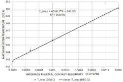
A trade study was performed on the thermal interface material providing thermal conductance between the various components in the system. Simulations were done for a range of contact heat-transfer coefficients for typical thermal interface materials in the commercial electronics cooling industry (ranging from a “very good” thermal interface to a “very poor” thermal interface). Figure 13 plots maximum temperature in the system versus thermal contact resistivity. As theory predicts, the trend is linear.
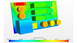
Figure 14 shows isothermal contours for a sub-module that has a very poor thermal contact interface. The image shows a wide range of temperatures, with the lowest temperature where the PCB card contacts the heat sink/cold plate assembly, to a highest value where the warmest component on the PCB is near the air flow region. Here, the impact of a poor thermal contact interface is profound, leading to a large temperature gradient across this particular sub-model.
Thermal Runaway
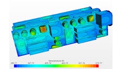
Thermal runaway due to faulty components in the system is readily predicted using this simulation approach. Figure 15 shows the result of a bad component (e.g., due to a manufacturing flaw or an internal short) on a particular PCB. The component experiencing thermal runaway is immediately identified as the outlier with very high temperature in Figure 15.
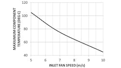
One common cause of failure in thermally controlled electronic systems is fan failure. This forces the thermal designer to use a redundant system, i.e., backup fans. To understand the effects of fan failure, various CFD simulations were performed at different airflow rates. Figure 16 is a plot of the system-level maximum component/chip temperature versus fan-air speed. The trend depicted is as expected, i.e., as the fan speed approaches zero, the various components and PC cards within the sub-modules will witness a large temperature. The results are in agreement with the trends in the studies of “CFD Analyses of a Notebook Computer Thermal Management System and a Proposed Passive Cooling Alternative”5 and “A CFD Based Analysis on the Effect of Free Stream Cooling on the Performance of Micro Processor Heat Sinks.” 6
Conclusion
STAR-CCM+ simulations of heat and fluid flow behavior in a moderately sized package of electronics undergoing very large power dissipations enabled the study of novel thermal control strategies at the system level. Results were in agreement with previous studies, and the approach used demonstrated quick and cost-effective evaluation of “cause-and-effect” scenarios for new electronics cooling solutions. This helps address the ever-changing requirements of delivering more power in smaller packages.
References
1. K.R. Anderson, M. Devost, W. Pakdee, N. Krishnamoorthy, “STAR-CCM+ CFD Simulations of Enhanced Heat Transfer in High-Power Density Electronics Using Forced Air Heat Exchanger and Pumped Fluid Loop Cold Plate Fabricated from High Thermal Conductivity Materials,” Journal of Electronics Cooling and Thermal Control, 2013, 3, 144-154.
2. “Thermacore k-Core Data Sheet,” 2013.
3. F. P. Incropera & D. P. Dewitt, Heat Transfer, McGraw-Hill, New York, 1991.
4. G. Ellison, Thermal Computations for Electronics—Conductive, Radiative, and Convective Air Cooling, CRC Press, Boca Raton, 2011.
5. I. Tari & Y. Fidan-Seza: “CFD Analyses of a Notebook Computer Thermal Management System and a Proposed Passive Cooling Alternative,” IEEE Transactions on Components and Packaging Technologies, Vol. 33, No. 2, 2010, pp. 443-452.
6. M.A. Ismail, M.Z. Abdullah & M.A. Mujeebu, “A CFD Based Analysis on the Effect of Free Stream Cooling on the Performance of Micro Processor Heat Sinks,” International Communications in Heat and Mass Transfer, Vol. 35, No. 6, 2008, pp. 771-778.
7. Y.A. Cengel, Heat Transfer—A Practical Approach, McGraw-Hill, New York, 2010.
