Interactive Graphical Interface Enhances Micro-Programmed Sequential Machine Design
This file type includes high-resolution graphics and schematics when applicable.
Different design approaches, techniques, and architectures are widely used for synchronous sequential machines. In particular, the micro-programmed machine approach offers important features such as speed, flexibility, a fixed hardware architecture, and a reduced instruction set (Count Conditional “CC”; Count Unconditional “CU”; Branch Conditional “BC”; Branch Unconditional “BU”; Count / Branch Conditional “CBC”). This has the objective of adapting the machine-design solution to the fixed hardware. Its main disadvantages are that it’s tedious and there’s a high probability of making mistakes in the process of manual instructions assembly.
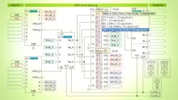
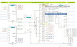
This article presents a Visual Basic (VB6) application that uses a graphical interface to allow for design process automation of a “four-bit slice” micro-programmed machine, with up to six input and four output variables and 16 possible states E0-E15 (Fig. 1). The solution generated with this software tool is a HEX file to be stored in the memory of the machine (IC4-IC5). The architecture of the machine can be simulated with some of the free tools offered by different hardware manufacturers and synthesized with medium-scale-integration (MSI) ICs or by using a complex programmable logic device (CPLD).
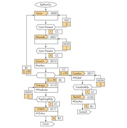
Like most Windows applications, the one shown here has a series of friendly menus that allows for the user file management, document editing, and micro-instructions assembly. To start the machine-design process with this tool, it’s necessary to have a state diagram or an ASM chart (Fig. 2), which represents the logical operation of the machine. The ASM chart shows the names and codes assigned to each state, input variables and micro-instructions to move from one state to another, and the immediate type outputs generated in the states.
This information will be entered into the graphical interface in the next possible order: inputs, outputs, names for states, and micro-instructions. To enter an input variable, place the mouse on one of the inputs of the multiplexers: Count Load (MuxCntLd) IC1 or Count Enable (MuxCntCe) IC2, click the left mouse button, and a gray text box will be displayed to edit the variable name; then click again the left mouse button to record changes. The same procedure is used to enter an output variable (Fig. 3).
To view: Enter or edit the name of each one of the states used and their corresponding micro-instruction; place the mouse over any of the E0-E15 labels located on IC4 and IC5; and then click the left mouse button to display two controls located to the right of the selected label. The first control displays the name assigned to the state, while in the second is the corresponding micro-instruction.
To change the displayed information: Place the mouse over one of the controls; make the necessary changes; and once again click the left mouse button over the control to record changes. When entering or changing the micro-instruction, click the left mouse button on the micro-instruction control and one control box with the possible micro-instructions displayed on the bottom of the control. Select the micro-instructions by clicking the left mouse button and the selected text is placed in the control of Micro-instruction.
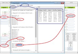
In the background screen (which usually is hidden), there’s a window titled "Assembler" that contains two text boxes—Code box and Hex box. All information presented in the graphical interface is stored in the Code box: input variables, output variables, names assigned to each of the states, and micro-instructions to move from one state to another. The Hex text box is used to display the HEX file as the result of the machine design generated when compiling the information contained in Code text box through the Assembly menu, as show in Fig. 3.
This tool has been used for educational purposes in Digital Design lectures offered at the School of Engineering of the Universidad Nacional Autónoma de México. However, it can be applied in other fields of knowledge with minor changes. To obtain an executable file of this application with limited functions, send an email request to [email protected] to download it from a Dropbox application folder.
Roberto Tovar and Román Osorio are at the Institute of Applied Mathematics and Systems, Universidad Nacional Autónoma de México; Tania Tovar is a postgraduate student in the School of Engineering at the same institution.

About the Author
Roberto Tovar
Design Engineer, Institute of Applied Mathematics and Systems, Universidad Nacional Autónoma de México
Roberto Tovar, an electronics engineer, is a professor at the School of Engineering of UNAM, and a full-time academic at IIMAS-UNAM. He has a master’s degree in electronics from School of Engineering of UNAM.
Comment About the Article
To join the conversation, and become an exclusive member of Electronic Design, create an account today!

Leaders relevant to this article: