Trusted Firmware Development for Connected Mobility Systems
What you’ll learn:
- Learn how disciplined firmware development practices help enable safe, secure, and reliable connected mobility systems.
- Discover how MISRA C, embedded security, automated testing, and CI/CD pipelines support functional safety and cybersecurity compliance in EV applications.
- Understand how traceability, regression testing, and compliance-ready evidence generation contribute to meeting the expectations of regulatory standards.

Reliable solutions in the connected mobility space, such as automotive applications, require a systematic approach to creating firmware.
This article focuses on key concepts of a suitable process including disciplined coding practices, embedded security, systematic testing, continuous integration and delivery (CI/CD), and finally traceability and compliance – and demonstrate their application in product development for electric-vehicle (EV) and connected mobility.
Let’s start with a basic question:
Why is a structured process needed at all?
Table of Contents
- The Challenge in Front of Us as Firmware Designers
- The Cost of Weak Engineering Discipline
- The Regulatory and Compliance Landscape
- A Practical Set of Principles
- Disciplined Coding
- Key Concepts of Safe Subset Coding
- Static Analysis
- Embedded Security
- Device-Local Security
- Communication Security
- Core Principles of Secure Communication
- Chain of Trust and Secure Boot
- Unit and Integration Testing
- Unit Testing
- Integration Testing
- Automation and Evidence Generation
- CI/CD and Regression Testing
- Pipeline Structure
- Regression Testing
- Traceability and Compliance
- Requirements Traceability Matrix
- So How Far Does This All Go Toward Regulatory Standards Compliance, Really?
The Challenge in Front of Us as Firmware Designers
We’re increasingly in a situation where engineers define system behavior through software and firmware. In EVs and smart mobility platforms, firmware determines how systems operate more than what’s possible with hardware.
Whether it has to do with battery management, motor torque control, braking systems, or communications, it relies on deterministic firmware behavior.
Even mid-tier vehicles today typically contain between 70 and 100 electronic control units (ECUs), and more than 100 million lines of code. This level of complexity — almost entirely contained in program code — makes correct behavior increasingly sensitive to programming defects.
A single instance of undefined behavior in a C function can propagate into a serious system-level failure.
Consider an example scenario. A missing volatile qualifier on a flag that’s updated inside an interrupt service routine can cause something like an EV charge-port lock to fail intermittently. Diagnosing that kind of issue can take months because the failure is subtle, timing-dependent, and difficult to reproduce consistently.
The Cost of Weak Engineering Discipline
This sensitivity to firmware defects only aggravates an environment in which historically, many embedded projects have relied on ad-hoc coding and manual testing, leading to several important consequences:
- There’s often a lack of robustness during integration. Individual modules may compile successfully, but they behave unpredictably together under certain conditions.
- Code updates and bug fixes may not be adequately verified. Without regression testing, there’s no objective evidence that changes didn’t introduce unintended side effects.
- Certification effort can become excessive. Gaps in manually collected test evidence often lead to multiple resubmissions, and unexpected side effects can render previous approvals invalid.
These issues could, in turn, result in high warranty costs from late-stage, in-field failures, and a loss of regulatory confidence in both the product and the organization.
As another example, consider a braking ECU that begins to exhibit communication timeout faults only after 10,000 km of fleet testing. The root cause turns out to be a missing boundary check. Proper unit testing would have revealed this defect much earlier.
The Regulatory and Compliance Landscape
Structured development isn’t just a matter of engineering preference — it’s required by the regulatory environment.
Firmware for EV and mobility systems must demonstrate traceable conformance to several frameworks:
- ISO 26262 for functional safety
- ISO/SAE 21434 for cybersecurity
- MISRA C and AUTOSAR C++14 for safe subset coding
- ASPICE (Automotive Software Process Improvement and Capability dEtermination) for process capability and lifecycle consistency
All of these standards formalize the engineering discipline that promotes safe and predictable system behavior.
Compliance requires objective supporting evidence — design artifacts, test results, and code quality metrics — not just claims of correctness.
A notable distinction here is that ISO 26262, ISO/SAE 21434, and MISRA focus on the quality of the engineering work itself, while ASPICE evaluates the maturity of the organization’s processes as it carries out that work.
A Practical Set of Principles
With that context in mind, the objective of this article will be to demonstrate a practical, interrelated set of principles for disciplined firmware development:
- Enforcing coding standards, particularly MISRA C
- Addressing embedded security considerations
- Applying unit and integration testing techniques
- Using continuous integration and delivery with automated regression testing
- Establishing traceability with supporting evidence for regulatory compliance
The aim is to provide both an initial understanding and some actionable insights into practices that the EV and connected mobility industry expects from developers of safe and reliable solutions.
Disciplined Coding
Why is disciplined coding essential?
As already pointed out, embedded software complexity is rising rapidly. With that comes an increased risk that undefined behavior during code execution could jeopardize functional safety. Preventing such behavior becomes a primary concern.
MISRA C and AUTOSAR C++14 define structured “safe subsets” of their respective languages. Because C remains widely used in embedded systems, the focus here is on MISRA C.
The purpose of a safe subset is to minimize ambiguity, enforce predictable behavior, and facilitate static analysis. This aligns directly with the intent of ISO 26262 — specifically Part 6, which addresses software. While ISO 26262 doesn’t mandate a specific safe subset, it does state that the use of language subsets is “highly recommended” and requires that “coding guidelines” be applied, explicitly citing MISRA C as a suitable approach.
Key Concepts of Safe Subset Coding
Safe subset coding works by selectively permitting certain language features and restricting others to reduce risk. For MISRA C, this is built around several core themes:
- Eliminating undefined and implementation-defined behavior
- Controlling scope and preventing unintended side effects
- Avoiding hidden type conversions and implicit promotions
- Enforcing clear control flow with traceable decision logic
The rules themselves are grouped by focus areas. For example:
- Rules 10.x and 11.x address data types, aiming to prevent overflow and ensure portability.
- Rules 13.x and 14.x focus on control flow, ensuring predictable and analyzable execution.
- Rules 18.x govern pointer usage, reducing risks associated with aliasing and indirection.
To illustrate, the following examples show typical violations and their corrections.
Example 1: Implicit Type Conversion
Non-compliant code (Rule 10.3 – composite expression causes hidden conversions):
int16_t speed;
uint8_t offset;
uint16_t result;

result = speed + offset; /* Implicit promotion, signed/unsigned mix */
Compliant correction (avoids risk of wrap-around):
int16_t  speed;
uint8_t  offset;
int32_t  result;

result = (int32_t)speed + (int32_t)offset; /* Explicit cast to preserve sign and range */
Example 2: Pointer Arithmetic
Non-compliant code (Rule 18.4 – pointer arithmetic not allowed):
uint8_t buffer[32];
uint8_t *ptr = buffer;
ptr += 5;
Compliant correction (avoids pointer increments, which complicate formal verification and safety analysis):
uint8_t buffer[32];
uint8_t *ptr = &buffer[5]; /* Direct indexing instead of arithmetic */
Example 3: Side Effects in Logical Expressions
Non-compliant code (Rule 13.5 – right hand operand of logical AND or OR causes side effects):
if (getVoltage() > threshold && incrementCounter())
{
    ...
}
Compliant correction (execution sequence becomes deterministic):
int16_t v = getVoltage();
if (v > threshold)
{
    incrementCounter();
}
These examples are intentionally simple, but they reflect the kinds of issues that MISRA C is designed to identify and eliminate. For those interested, reviewing such examples in detail can provide a deeper appreciation of the subtleness of some of these risks.
Static Analysis
Static-analysis tools are commonly used to enforce safe subset rules in practice. Examples include PC-lint, LDRA Testbed, Coverity, and the open-source tool Cppcheck.
These tools are typically integrated into a CI pipeline so that rule checking is applied automatically; often before code is allowed to be merged into a main branch. A common practice is to require zero critical violations for a build to be accepted. In addition, such tools generate MISRA compliance reports that serve as supporting evidence during audits. If deviations from MISRA rules are justified, they must be documented and formally approved.
As a final remark on disciplined coding, it’s important to realize that static-analysis tools don’t replace human code reviews. Rather, they allow reviewers to focus on design intent and system behavior instead of rule syntax.
Embedded Security
The discussion now shifts from how we write code to what we must implement to achieve cybersecurity compliance.
The “how” of safe subsets is a key common denominator when it comes to functional safety and ISO 26262. For cybersecurity and ISO/SAE 21434, on the other hand, “what” features to implement can be seen as very much the important common denominator for connected mobility in general.
However, it’s also important to understand that ISO/SAE 21434 mandates security objectives, not specific implementations such as those to be mentioned shortly for device-local and communication security. For example, a rule may be in the spirit of the statement, “shall protect an asset’s integrity,” not “shall apply a digital signature to all firmware images.” While ISO/SAE 21434 doesn’t prescribe specifics, this section of the article offers some specific practical approaches.
Device-Local Security
Even if a device runs functionally safe code, it’s not secure if it can be maliciously compromised.
In the EV domain, devices must satisfy cybersecurity requirements defined by ISO/SAE 21434 to be acceptable. Though not specifically mandated, recommended device-level security measures include:
- Disabling diagnostic and debugging interfaces (such as serial ports) in production devices.
- Restricting access if such interfaces must remain enabled; for example, by eliminating default passwords.
- Implementing tamper protection, such as wiping memory if tampering is detected.
- Encrypting sensitive data at rest (e.g., using AES-128), with keys stored in a hardware secure element.
- Implementing secure boot to prevent unauthorized firmware from executing.
These are representative examples intended to illustrate common expectations, rather than an exhaustive list.
Communication Security
Modern EVs are highly connected systems. They communicate with cloud services and other vehicles and infrastructure (V2X), as well as receive over-the-air updates. This connectivity introduces a broad attack surface. Potential entry points include wireless networks and in-vehicle communication buses such as CAN and LIN, especially when exposed through gateways.
Security attacks in this context can have real-world consequences, including manipulation of vehicle control systems. Failures in security could compromise both safety and privacy, and it may lead to non-compliance with regulatory requirements. Therefore, appropriate measures to secure communication must be taken to minimize the risk of compromise.
Core Principles of Secure Communication
Secure communication rests on four key principles:
- Confidentiality: Protecting messages from eavesdropping using encryption (e.g., TLS for cloud communication, AES for local communication)
- Integrity: Ensuring that data can’t be altered during transmission (e.g., using message authentication codes or digital signatures).
- Authentication: Verifying the identity of communicating entities (e.g., using digital signatures and certificates)
- Non-repudiation: Preventing entities from plausibly denying actions they performed (e.g., using digital signatures)
Each layer of the EV communication stack, from CAN gateways to cloud APIs, should enforce the principles appropriate in each case.
Non-repudiation is perhaps most familiar in financial transactions. For instance, it could be meaningful for connected mobility when a vehicle requests paid charging services and can’t later deny making that request.
The diagram of Figure 1 helps to clarify the principles of confidentiality and integrity.
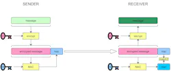
The typical procedure is for the sender of a message to use a key (here labeled E) to encrypt the message, and a second key (labeled M) to compute a message authentication code over the encrypted message.
When the receiver receives the message, it recomputes the MAC over the encrypted message using the same key M That it also possesses. Then it compares the result to the one that arrived with the message. If the two match, the receiver knows the message wasn’t damaged or tampered with in transit.
The receiver then decrypts the message, being in possession also of key E, and the encryption being usually some symmetric algorithm like AES.
Figure 2 illustrates the concept of digital signing and signature verification commonly used in implementing integrity, authentication or non-repudiation.
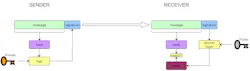
The sender first computes a hash over the message it will be sending, and it’s the owner of a private key that it applies along with the hash to a signature function.
The receiver possesses the public key corresponding to the sender’s private key and applies it along with the signature in the received message to a function that recovers the hash. It also recomputes the hash over the received message. If the two hashes match, the receiver knows the message is authentic and was sent by the holder of the private key.
Digital signature and verification of OTA firmware images employ the same principle. Also, the same diagram applies if we simply replace “SENDER”, “RECEIVER”, and “message” with “SERVER”, “EMBEDDED DEVICE“, and “image file”, respectively.
Chain of Trust and Secure Boot
Secure boot (Fig. 3) was already mentioned in the section on device-local security. It establishes a chain of trust within the device, with a secure bootloader at the top of the chain acting as the root of trust. In this role, it must be protected against read and write access. Its sole function is to verify the signature of the second-stage bootloader and then jump to it.
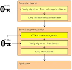
In fact, this is how the chain of trust is maintained. As shown in the diagram, each stage must verify the signature of the next stage before trusting it to execute and jumping to it.
Firmware image signing ensures the authenticity of updates. The second-stage bootloader verifies downloaded application images before installation and verifies the active image before execution.
Only the public keys used for signature verification are stored on the device, while the private keys that signed the images must be kept secure and never be sent to the device.
Now the reader may be wondering, why do we have two bootloader stages? Why not move OTA update management into the root of trust and have just a single bootloader? There are two main reasons:
- The attack surface is minimized for the first stage — understandably important for a root of trust — by keeping it simple and not giving it network communication capability.
- Any higher functionality like OTA can be updated if it’s ever necessary because it resides in the second stage, the first stage not being writeable.
Unit and Integration Testing
Returning to the “how” side of firmware development, testing is a critical component.
Embedded software failures often originate from subtle logic errors or unchecked boundary conditions. Testing early, at appropriate levels, and with sufficient thoroughness helps prevent costly defects from appearing in the field.
The two key levels are unit testing and integration testing.
Unit Testing
Unit testing involves implementing isolated tests for individual modules.
Functions designed with simple inputs and outputs are easier to test effectively. Test cases should cover normal inputs, boundary conditions, invalid ranges, and edge cases. Typical areas covered include range checks, state-machine transitions, arithmetic overflow, and error handling.
One useful way to think about unit testing is that it catches bugs before integration has a chance to hide them.
The simplified C code below demonstrates a common pattern followed for unit testing. A battery module in the hypothetical firmware-under-test called battery.c contains a function for calculating state of charge and a function for detecting an overvoltage condition. A unit test module called test_battery.c implements code that calls those functions with different combinations of input parameters.
Testing passes or fails depending on whether the state of charge and overvoltage functions output the expected result for each input combination, and log messages are reported accordingly.
/* === battery.c === */
float calculate_soc(float voltage, float capacity) {
    if (capacity <= 0) {
        return -1;
    }
    return (voltage / capacity) * 100.0f;
}

int is_overvoltage(float voltage, float max_voltage) {
    return voltage > max_voltage;
}           /* === test_battery.c === */

void test_calc_soc_normal(void) {
    float soc = calculate_soc(48.0f, 60.0f);
    assert(soc == 80.0f);
}

void test_calc_soc_bad_capacity(void) {
    float soc = calculate_soc(48.0f, 0.0f);
    assert(soc == -1);  // error value
}

void test_is_overvoltage(void) {
    assert(is_overvoltage(42.0f, 40.0f) == 1);
    assert(is_overvoltage(38.0f, 40.0f) == 0);
}

int main(void) {
    test_calc_soc_normal();
    test_calc_soc_bad_capacity();
    test_is_overvoltage();
    printf("All BMS unit tests passed!\n");
    return 0;
}
Integration Testing
Integration testing focuses on how modules interact with each other.
It verifies that modules work together correctly in realistic scenarios. Integration testing addresses issues such as timing assumptions, sequencing dependencies, and alignment of protocol implementations and message formats.
The example code below shows what a simplified integration test might look like for verifying the interaction between two modules in the firmware-under-test, battery.c and motor.c. (Note that the struct declarations for BatMgmt, ChrgSys and MotorCtrl have been omitted for simplicity.)
First, to have some interaction between the battery and motor that can be tested, the motor code has logic implementing a requirement that the motor doesn’t run while the battery is charging, and the battery code implements a requirement that prevents the battery from charging when there’s an overvoltage condition.
/* === battery.c === */
void bms_update(BatMgmt *bms) {
    bms->overvoltage = is_overvoltage(bms->current_voltage,
                                      bms->max_voltage);
}

int bms_is_safe(const BatMgmt *bms) {
    return !bms->overvoltage;
}

int start_charging(ChrgSys *cs, const BatMgmt *bms) {
    if (!bms_is_safe(bms)) {
        printf("Charging aborted: unsafe battery.\n");
        cs->active = 0;
        return -1;
    }
    cs->active = 1;
    printf("Charging started.\n");
    return 1;
}

void stop_charging(ChrgSys *cs) {
    cs->active = 0;
    printf("Charging stopped.\n");
}

/* === motor.c === */
void motor_update(MotorCtrl *mc, ChrgSys *cs) {
    if (cs->active) {
        mc->enabled = 0;
        printf("Motor disabled (charging active).\n");
    } else {
        mc->enabled = 1;
        printf("Motor enabled.\n");
    }
}
/* === test_battery_and_motor.c === */
int main(void) {
    BatMgmt bms  = { .current_voltage = 380.0f,
                     .max_voltage = 400.0f };
    ChrgSys cs   = { .active = 0 };
    MotorCtrl mc = { .enabled = 1 };
    bms_update(&bms);

    int result = start_charging(&cs, &bms);
    motor_update(&mc, &cs);
    assert(result == 1);
    assert(cs.active == 1);
    assert(mc.enabled == 0); /* Motor should be disabled
                                while charging */
    // Now simulate overvoltage condition
    bms.current_voltage = 420.0f;
    bms_update(&bms);
    result = start_charging(&cs, &bms);
    motor_update(&mc, &cs);
    assert(result == -1);
    assert(cs.active == 0);
    assert(mc.enabled == 1); /* Motor can be re-enabled
                                if not charging */
    printf(“Battery and motor test passed.\n");
    return 0;
}
The integration testing module called test_battery_and_motor.c demonstrates first sets up a state with charging off and the motor enabled. Then it initiates charging and verifies that the motor goes to the disabled state.
The module then simulates an overvoltage condition, verifies that an attempt to initiate charging fails, and that in this case the motor can be enabled because the battery isn’t being charged.
Automation and Evidence Generation
The next section discusses how execution of unit and integration tests becomes automatic and consistent when they’re incorporated into a CI/CD pipeline.
And later it will be demonstrated how unit and integration test results become auditable evidence for:
- Functional-safety cases under ISO 26262
- Cybersecurity requirements under ISO/SAE 21434
CI/CD and Regression Testing
Manual build processes and ad-hoc testing inevitably lead to inconsistent quality. Automated CI/CD pipelines ensure that the same steps are executed consistently for every build.
These pipelines automate firmware building and testing using platforms such as Azure DevOps, Jenkins, or GitLab CI.
CI/CD is also highly practical for regulatory compliance, although not mandatory. It’s a common approach to maintaining the consistent and thorough evidence collection demanded across repetitive audit cycles, and throughout an EV product’s evolution over its lifetime.
In practice, CI/CD is often referred to simply as CI. Indeed, continuous delivery alludes essentially to readying a product automatically for release, but it’s primarily in continuous integration that product development and evidence generation primarily occur.
Pipeline Structure
A typical CI pipeline includes:
- Static analysis (with MISRA reporting)
- Firmware build
- Unit testing
- Integration testing
- Artifact packaging
The artifact package contains all outputs relevant to compliance audits, including firmware images, manifests, metadata, and test reports.
Regression Testing
Regression testing is the primary purpose of CI. Each time a new build is created, all tests — static analysis, unit tests, and integration tests — are rerun.
Regression refers to the unintended introduction or reintroduction of defects following changes such as bug fixes or enhancements. Automated regression testing ensures that new updates don’t break existing behavior.
When a defect is discovered in the field, its fix must include a corresponding regression test. And naturally it will, since it’s the CI pipeline that produces a new build from the corrected code.
Keeping everything in perspective, we should point out that automatic regression testing doesn’t eliminate the need for manual regression testing. For example, manual testing must still be used when proof of human safety depends on the user’s experience, such as by their interaction with a user interface, or when automatically obtaining feedback of a test’s result is not practical.
Furthermore, human maintenance of the automated regression testing is necessary; for instance, adding new unit and integration tests to support new product features.
The next section will explain how to organize regression test data and results into traceable compliance-ready evidence.
Traceability and Compliance
Traceability is what ties everything together. It links requirements to design, code, and tests. These traceable links form the core of compliance evidence. Traceability supports:
- Functional-safety audits (ISO 26262)
- Cybersecurity audits (ISO/SAE 21434)
- ASPICE process assessments
Without traceability, a bug may be missed because there’s no clear link between a requirement and a test verifying the requirement’s implementation.
Regulatory compliance auditors need evidence that every safety and security requirement has been implemented and verified. Traceability makes audits systematic by clearly demonstrating coverage of requirements.
Requirements Traceability Matrix
The primary tool for documenting traceability is the Requirements Traceability Matrix (RTM). An RTM links each requirement to:
- Its implementation in code.
- The test cases that verify it.
- The results and associated artifacts.
An RTM capturing the example tests that were demonstrated previously would look something like the following table.
| Req ID | Requirement | Implementation | Test Case | Test Code | Test Result | Evidence / Artifact |
|---|---|---|---|---|---|---|
| R-128 | The system shall calculate state-of-charge as a percentage. | battery.c [calculate_soc] | TC_U_001 | test_battery.c [test_calc_soc_normal, test_calc_soc_bad_capacity] | Pass | test\uni_20250101_001.log |
| R-129 | The system shall detect an overvoltage condition. | battery.c [is_overvoltage] | TC_U_002 | test_battery.c [test_is_overvoltage] | Pass | test\uni_20250101_001.log |
| R-130 | The system shall enable the motor only when not charging the battery. | motor.c [motor_update] battery.c [bms_update, bms_is_safe, start_charging, stop_charging, is_overvoltage] |
TC_I_013 | test_battery_and_motor.c [main] | Pass | test\int_20250101_002.log |
Each row links a clearly identified firmware requirement to:
- The related functions in the battery.c and motor.c modules that implement it in the firmware-under-test.
- The test case and unit or integration test code module and function that verifies it, along with the test result and report log.
In the interest of correctness, it should be noted that the earlier example code and this RTM are for the purpose of clarifying concepts and some aspects may not be entirely practical.
For instance, if requirement R-129 in the table is to be tested measurably, instead of its description reading simply, “The system shall detect an overvoltage condition”, it should read isomething like, “The system shall detect an overvoltage condition when any cell voltage exceeds 4.25 V for longer than 100 ms.”
So How Far Does This All Go Toward Regulatory Standards Compliance, Really?
The practices described here are necessary for supporting regulatory standards in safety-critical connected mobility systems:
- Traceability is needed between software requirements and test evidence, for both functional safety (ISO 26262) and cybersecurity (ISO/SAE 21434).
- CI/CD and regression Testing ensure consistent evidence collection mandated by ISO 26262 and ISO/SAE 21434.
- Unit and integration testing verify implemented requirements to the level mandated by ISO 26262.
- The Embedded Security recommendations commonly must be implemented in a project to satisfy ISO/SAE 21434.
- The Disciplined Coding guidance aligns with ISO 26262’s call for unambiguous intent and predictable behavior.
- From the perspective of ASPICE, all of the consistent prudence in execution at the project level reflects process maturity at the company level, as your organization performs engineering activities.
At the same time, note that the practices recommended play only a part (albeit an important one) toward completely fulfilling compliance criteria. For example:
- ISO 26262 further mandates analyzing the hazards that lead to safety goals, and in turn to system and then software requirements.
- ISO/SAE 21434 similarly positions threats, cybersecurity goals, and system requirements ahead of cybersecurity requirements.
- ASIL D (ISO 26262) classifies EV and connected mobility products where life safety is a top priority. Organizations usually must have ASPICE Level 3 certification to become a supplier of these products, and there are other organizational process maturity prerequisites to becoming Level 3 qualified.
Nevertheless, the foregoing approach facilitates development of reliable firmware from the safety and cybersecurity perspectives of ISO 26262 and ISO/SAE 21434, and it provides strong support toward achieving ASPICE Level 1 or Level 2.
>>Download the PDF of this article
 promo_transportation_dreamstime_371961785
About the Author
 Dayman Pang
Dayman Pang
Firmware Team Lead, NeuronicWorks Inc.
Dayman Pang is the firmware team lead at NeuronicWorks, a company specializing in embedded systems design. He is a licensed Professional Engineer who holds a Master of Engineering degree from the University of Toronto.
Comment About the Article
To join the conversation, and become an exclusive member of Electronic Design, create an account today!
 Leaders Logo
Leaders relevant to this article: