Materials Characterization: Resistivity measurements using a four-point collinear probe

Electrical resistivity is a basic property that quantifies a material’s opposition to current flow—it’s the reciprocal of conductivity. The resistivity of a material depends upon several factors, including the material doping, processing, and environmental factors such as temperature and humidity. The resistivity of the material used in a device can affect its characteristics, such as the series resistance, threshold voltage, and capacitance.
The need to measure the resistivity of a material is common in both research and fabrication applications. There are many methods for determining the resistivity of a material, but the technique may vary depending upon the type, the magnitude of the resistance, the shape, and the thickness of the material. One of the most common ways of measuring the resistivity of some thin, flat materials, such as semiconductors or conductive coatings, uses a four-point collinear probe.
The four-point probe technique involves bringing four equally spaced probes in contact with a material of unknown resistance. A DC current is forced between the outer two probes, and a voltmeter measures the voltage difference between the inner two probes. The resistivity is calculated from geometric factors, the source current, and the voltage measurement. Along with a four-point collinear probe, the instrumentation used for this test includes a DC current source and a sensitive voltmeter. To simplify measurements, an integrated parameter analyzer featuring multiple source measure units along with control software can be used for a wide range of material resistances including very high-resistance semiconductor materials.
Using a four-point probe
To use a four-point collinear probe, the probe array is placed in the center of the material (Figure 1).

The two outer probes are used for sourcing current, and the two inner probes are used for measuring the resulting voltage drop across the surface of the sample. The volume resistivity is calculated as follows:
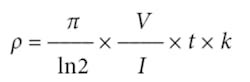
where: ρ = volume resistivity (Ω-cm)
V = the measured voltage (V)
I = the source current (A)
t = the sample thickness (cm)
k = a correction factor based on the ratio of the probe to wafer diameter and on the ratio of wafer thicknessto probe separation
For some materials such as thin films and coatings, the sheet resistance, or surface resistivity, is determined instead, which does not take the thickness into account. The sheet resistance (σ) is calculated as follows:
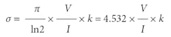
where: σ = the sheet resistance (Ω/square or just Ω)
Note that the units for sheet resistance are expressed in terms of Ω/square in order to distinguish this number from the measured resistance (V/I).
Eliminating lead, contact resistance
Using four probes eliminates measurement errors that can result from probe resistance, the spreading resistance under each probe, and the contact resistance between each metal probe and the semiconductor material. Figure 2 is another representation of the four-point collinear probe setup showing some of the circuit resistances. The RL terms represent test-lead resistance. RC represents contact resistance between the metal probe and the semiconductor material. The contact resistance can be several hundred to a thousand times higher than the resistance of the sample material represented by RS.
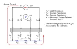
The current flows through all the resistances in the first and fourth sets of leads and probes as well as through the semiconductor material. However, the voltage is only measured between probes 2 and 3. Given that between probes 2 and 3 the current only flows through RS2, only the voltage drop due to RS2 will be measured by the voltmeter. All the other unwanted lead (RL) and contact (RC) resistances will not be measured.
For successful resistivity measurements, potential sources of errors need to be considered.
Electrostatic interference
Electrostatic interference occurs when an electrically charged object is brought near an uncharged object. Usually, the effects of the interference are not noticeable because the charge dissipates rapidly at low-resistance levels. However, high-resistance materials do not allow the charge to decay quickly, and unstable measurements may result. The erroneous readings may be due to either DC or AC electrostatic fields.
To minimize the effects of these fields, an electrostatic shield can be built to enclose the sensitive circuitry. The shield should be made from a conductive material and connected to the low-impedance (FORCE LO) terminal of the test instrument. The cabling in the circuit also must be shielded.
Leakage current
For high-resistance samples, leakage current may degrade measurements. The leakage current is due to the insulation resistance of the cables, probes, and test fixturing. Leakage current may be minimized by using good quality insulators, reducing humidity, and using guarding.
A guard is a conductor connected to a low-impedance point in the circuit that is nearly at the same potential as the high-impedance lead being guarded. Using triax cabling and fixturing will ensure that the high-impedance terminal of the sample is guarded. The guard connection also will reduce measurement time since the cable capacitance will no longer affect the time constant of the measurement.
Light
Currents generated by photoconductive effects can degrade measurements, especially on high-resistance samples. To prevent this, the sample should be placed in a dark chamber.
Temperature
Thermoelectric voltages may affect measurement accuracy. Temperature gradients may result if the sample temperature is not uniform. Thermoelectric voltages also may be generated from sample heating caused by the source current. Heating from the source current will more likely affect low-resistance samples because a higher test current is needed to make the voltage measurements easier.
Temperature fluctuations in the laboratory environment also may affect measurements. Because semiconductors have a relatively large temperature coefficient, temperature variations in the laboratory may need to be compensated for by using correction factors.
Carrier injection
To prevent minority/majority carrier injection from influencing resistivity measurements, the voltage difference between the two voltage sensing terminals should be kept at less than 100 mV, ideally 25 mV, since the thermal voltage, kt/q, is approximately 26 mV. The test current should be kept as low as possible without affecting the measurement precision.
Conclusion
A four-point collinear probe in conjunction with a parameter analyzer is a proven method for determining the resistivity of thin, flat materials such as semiconductors or conductive coatings. Some parameter analyzers may provide built-in configurable tests that include the necessary calculations. For successful measurements, it’s important to consider potential sources of error including electronics interference, leakage current, and environmental factors such as light and temperature. Resistivity can impact the characteristics of a device, serving as a reminder of the importance of making accurate and repeatable measurements.
About the author
Mary Anne Tupta is a senior applications engineer in the Keithley Instruments Product Line at Tektronix in Cleveland, OH. She has an M.S. degree in physics and a B.S. in physics/electronic engineering from John Carroll University. Tupta has been an applications engineer at Keithley since 1988. [email protected]
Editor’s note
This article is adapted from the application note “Resistivity Measurements of Semiconductor Materials Using the 4200A-SCS Parameter Analyzer and a Four-Point Collinear Probe,” Tektronix, 2016.

Comment About the Article
To join the conversation, and become an exclusive member of Electronic Design, create an account today!

Leaders relevant to this article: