Improve Industrial Functional-Safety Compliance with Voltage Supervisors (Part 1)
What you'll learn:
- Details of the IEC 61508 functional-safety standard.
- Use of supervisory circuits to achieve functional-safety compliance.
- Safety integrity requirements of IEC 61508-1.
- Architectural constraints of a safety instrumented system.
Compliance to functional safety is usually considered in safety-critical applications across various industries1 where failures can inflict harm to people, properties, and environment. Product designers certify their designs to functional-safety standards so that their customers have confidence to use their products, to market their products in countries with safety regulations, and to lead the functional-safety market trend.
This article highlights the value of high-performance supervisory circuits2 in enhancing compliance with functional-safety standards like IEC 61508.3 In addition, it’s the first in a series discussing industrial functional-safety compliance in relation to these circuits.
Understanding the Functional-Safety Standards
The IEC 61508 standard,3 otherwise known as the Functional Safety of Electrical/Electronic/Programmable Electronic Safety-Related Systems, aims to provide the overall requirements for specification, design, and operation of all types of E/E/PE safety-related systems (SRS). It’s applicable across all sorts of industries, serving as the basis for development of several sector-specific standards such as IEC 615114 in the process industry, IEC 620615 in machinery, IEC 615136 in the nuclear power industry, ISO 262627 in the automotive industry, IEC 622798 in railway transport, IEC 623049 in medical devices,10 and others (Fig. 1).
While a sector-specific standard will always take precedence over IEC 61508, it typically requires using components in the SRS that proves its compliance to functional-safety standards. This can be achieved by developing components according to a sector-specific standard like ISO 26262,7 employing a Proven-In-Use3 argument, following the basic safety standard IEC 61508 (e.g., IEC 6151111), or using standard components but taking additional architectural mitigations.
What’s a Safety Instrumented System?
IEC 61508’s E/E/PE SRS is termed as safety instrumented system (SIS) in the process industry sector, safety-related electrical control system (SRECS) in machinery, and instrumentation and control (I&C) system in the nuclear power industry. In this article, the term SIS will be used to generalize these systems.11
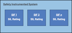
Figure 2 illustrates a typical SIS that includes at least one safety instrumented function (SIF). SIF also refers to safety functions in IEC 61508, but for the purpose of discussion, the term SIF will be used. A SIF consists of an input subsystem, logic solver subsystem, and final element subsystem, all aimed at placing the equipment under control (EUC) into a safe state upon occurrence of a demand. The EUC refers to the system being protected by the SIS.
Figure 3 shows a typical block diagram of a SIF as well as examples of the subsystems. The input subsystem, consisting of at least one sensor, acts as a monitoring system that can detect failures and sends a signal to the logic solver. The logic solver processes the received signals and then decides the next step. This can demand the final element to place the SIS into a safe state through actuating devices such as circuit breakers, relays, or shutdown valves.11
Notably, supervisory circuits2 are useful in SISs. They can function in an input subsystem to detect abnormalities, in a logic solver subsystem to monitor the power supply or other microcontroller functions and signal failures, or as the SIF itself, bringing the system into a safe state through a reset signal (Fig. 3, again).
How High-Performance Supervisory Circuits Enable Compliance with Industrial Functional Safety
Compliance to IEC 61508 can be quantized through the safety integrity level (SIL). SILs are rated for each SIF and denote how well a SIF performs its job in managing the risk. IEC 61508 specifies four levels of SIL from SIL 1 to SIL 4, with SIL 4 being the most reliable. Typically, a hazard analysis and risk assessment is first done to know the required safety functions and, subsequently, the risk-reduction factor, or SIL rating, needed. One method of doing this is shown in the Process Safebook 112 with the risk-matrix calibration.
A specific SIL level has its own requirements affected by three factors: Quantitative reliability requirements, architectural constraints, and systematic safety integrity.3,11,13 For each factor, the next section will show how supervisors can help achieve IEC 61508 compliance through its diagnostic requirements.
Quantitative Reliability Requirements
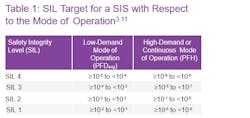
Table 1 shows the summary of the safety integrity requirements of IEC 61508-1 under section 7.6.2.9 specifying SIL with respect to the target failure measure of a SIF. PFDavg refers to the average probability of dangerous failure on demand of the safety function for a low-demand mode of operation. PFH refers to the average frequency of a dangerous failure of the safety function per hour for a high-demand mode or continuous mode of operation.
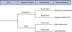
Among the several factors affecting the average probability of random hardware failures are the diagnostic test coverage, diagnostic test interval, and the dangerous undetected failure rate as denoted by λDU.3,14,15 Dangerous undetected failures are those that can’t be detected by a system’s diagnostics and can only be identified through a proof test as shown in Figure 4.
This is where the importance of using supervisory circuits comes into play, as they aid in the detection of dangerous failures by acting as diagnostic measures to reduce the probability of such failures. Thus, they convert dangerous undetected failures into detected ones.
Architectural Constraints
Aside from the quantified reliability requirements, IEC 61508 provides requirements for the robustness and structure of the SIS. These architectural constraints add to the considerations needed by the designer when it comes to choosing the hardware architecture. Under IEC 61508-2 section 7.4.4, one of the routes that can be used to show compliance to SIL is Route 1H. This route is based on the hardware fault tolerance (HFT) and safe failure fraction (SFF) concepts.
Architectural constraints require consideration of the complexity and type of element. A Type A element, or simple component, has well-defined failure modes, predictable behavior under fault conditions, and reliable failure data meeting the required dangerous undetected failure rate. Otherwise, it’s considered a Type B element or complex component.
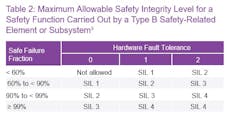
Table 2 shows the requirements for a Type B element, which takes electronic systems such as integrated circuits, as an example. SFF is a measure of the tendency of an element to fail toward a safe state. HFT of N means that N+1 is the minimum number of faults that could cause a loss of the safety function and, in turn, require a certain amount of redundancy. Thus, if a system has an HFT of 0, a single failure can cause a loss of the safety function, whereas an HFT of 1 means it will take two failures to cause such loss.
Mathematically, SFF can be expressed as:
Another term called the diagnostic coverage can be expressed as:
where λ is the failure rate, SD is for safe detected, SU is for safe undetected, DD is for dangerous detected, and DU is for dangerous undetected as seen in Figure 4.
This diagnostic coverage evaluates how well the diagnostic measures of a SIS perform in revealing dangerous failures. It also affects the quantified reliability of the system as previously discussed and is related to the SFF as seen in Equations 1 and 2. Furthermore, IEC 61508-2 in its Annex A has a way to determine the maximum allowable diagnostic coverage that can be claimed using different techniques and measures to detect random hardware failures.
Table 3 shows this via the diagnostic coverage classification with respect to the designation.
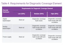
Table 4 shows a section of the IEC 61508-2 Annex A Table A.1, specifying the faults or failures to be assumed when quantifying the effect of random hardware failures or to be considered in the derivation of SFF. It can be noted that the diagnostic coverage fault model is required to claim a high diagnostic coverage. The diagnostic-coverage fault model includes failure modes such as stuck-at faults, stuck-open, open or high-impedance outputs, and short circuits between signal lines—all of which can be detected by supervisory circuits like overvoltage (OV) and undervoltage (UV) monitors.
In summary, IEC 61508 specifies a SIL requirement depending on the HFT and SFF of the SIF. With the SFF and diagnostic-coverage parameters being significantly affected by the system’s ability to detect faults, improving the diagnostic measures such as adding supervisory circuits will also enhance the SIL rating of the SIF.
Systematic Safety Integrity
The requirements for systematic safety integrity are qualitative in nature and assess how good the development process of the system is in eliminating failures. With this, a thorough examination of the design, production, and test procedures for both hardware and software is needed. The higher the SIL, the more stringent the examination must be, and more documentation is required to prove compliance that shall be provided by component manufacturers.
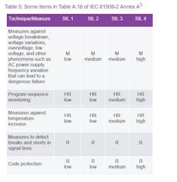
IEC 61508 specifies several techniques and measures that designers shall implement whenever applicable to eliminate systematic failure in various phases of the SIS’s safety lifecycle. Table 5 shows some items in Table A.16 of IEC 61508-2. This table reveals the techniques and measures needed to control systematic failures caused by environmental stress and influences, where M means mandatory, HR means highly recommended, and R means recommended.
Below these markings are the level of effort required to cover such diagnostic measures. For instance, it’s mandatory for a SIL 3 rating to employ measures against voltage variations such as voltage monitors, while highly recommended to have program sequence monitoring like watchdog timers, where the diagnostic coverage must be at least 90%.
Another key for the systematic safety integrity requirement is a good quality management system (QMS). This can be demonstrated by certifying the organization with the ISO 9001:2015 Quality Management Systems.16
The bulk of the requirements of IEC 61508 regarding the overall safety lifecycle and functional-safety assessment coincides with ISO 9001’s requirements for the overall safety lifecycle. Thus, having the QMS certificate can contribute to a faster certification process.17 This is alongside an organization’s strategy for functional safety, such as having its own adaptation of functional-safety standards like IEC 61508.
Using Integrated Solutions to Improve Functional-Safety Design
Designing systems with functional-safety compliance requires careful consideration of the requirements discussed earlier. This involves implementing adequate safety measures to ensure reliable and safe operation in case of failure, which may lead to an increase in circuit components and, consequently, costs. As a result, using components with integrated safety functions can simplify system-level implementation, improve system reliability due to reduced component count, and increase diagnostic coverage with lower diagnostic test intervals.13
This can be seen in Figure 5—showing how Analog Devices’ MAX42500 can provide enough diagnostic coverage to safety-critical circuits through its several safety features combined in one package, rather than using separate supervisory circuits. This power system monitor helps with functional-safety compliance by addressing the requirements regarding measures against voltage breakdown, voltage variations, overvoltage, low voltage, and other phenomena such as AC power-supply frequency variation (which can lead to a dangerous failure), and program sequence monitoring.
The first requirement emphasizes the necessity of UV and OV detection for all safety-critical voltage rails. The second requirement highlights the need for a separate watchdog timer for standard microcontroller units in single-channel systems. Both needs are met by the MAX42500, which features seven power-supply monitors and a watchdog timer via I2C communication.
Another consideration is the availability of safety documentation to prove functional-safety compliance, more so required when certifying for a functional-safety standard. Components compliant or certified to IEC 61508, such as the MAX42500, already support this by having the necessary safety documents—safety manual, failure modes effects and diagnostics analysis (FMEDA), good QMS, etc.—available on-hand.
Despite this, noncompliant products such as the LTC2965 and LTC4365 can still be utilized (Fig. 5, again) to improve diagnostic coverage and robustness of the system considering the IEC 61508’s current revision. However, system designers will need to acquire the necessary safety documentation for their functional-safety compliance requirements.
Meeting Functional-Safety Compliance with Supervisory Circuits
This article has shed light on the crucial role of high-performance voltage supervisors in facilitating industrial functional-safety compliance. By exploring the foundational functional-safety standard, IEC 61508, and its implications for sector-specific standards, a groundwork for understanding has been laid. In addition, key terms have been defined to provide clarity, such as safety instrumented system, safety instrumented function, and safety integrity level.
We also delved into IEC 61508’s essential requirements, including quantified reliability, architectural constraints, and systematic safety integrity, with a particular emphasis on the impact of employing high-performance supervisory circuits like power-supply monitors and watchdog timers. The utilization of integrated safety features has been discussed, exemplified by the MAX42500, to consider broader aspects in system design beyond functional-safety compliance.
Stay tuned for the next article in the series where we will discuss the advantages of using SIL-rated voltage supervisors when designing functionally safe power systems for safety-critical applications.
References
1. Tom Meany. “Functional Safety and Industry 4.0.” Analog Devices, Inc., March 2018.
2. Noel Tenorio and Anthony Serquiña. “High Performance Voltage Supervisors Explained–Part 1.” Analog Dialogue, Vol. 58, No. 2, April 2024.
3. IEC 61508 All Parts, Functional Safety of Electrical/Electronic/Programmable Electronic Safety-Related Systems. International Electrotechnical Commission, 2010.
4. IEC 61511 All Parts, Functional Safety–Safety Instrumented Systems for the Process Industry Sector. International Electrotechnical Commission, 2016.
5. IEC 62061–Safety of Machinery– Functional Safety of Safety-Related Electrical, Electronic, and Programmable Electronic Control Systems. International Electrotechnical Commission, 2005.
6. IEC 61513–Nuclear power plants-Instrumentation and control important to safety-General requirements for systems. International Electrotechnical Commission, 2011.
7. ISO 26262 All Parts, Road Vehicles Functional Safety. International Organization for Standardization, 2011.
8. IEC 62279. Railway Applications-Communication, Signaling and Processing Systems: Software for Railway Control and Protection Systems. International Electrotechnical Commission, 2015.
9. IEC 62304–Medical Device Software–Software life cycle processes. International Electrotechnical Commission, 2006.
10. FAQs: Functional Safety for Medical Devices. TÜV SÜD, 2024.
11. Marvin Rausand. Reliability of Safety Critical Systems: Theory and Applications. Wiley, January 2014.
12. Process Safebook 1: Functional Safety in the Process Industry. Rockwell Automation, March 2013.
13. Tom Meany. “Functional Safety for Integrated Circuits.” Analog Devices, Inc., February 2018.
14. Loren Stewart. “Back to Basics 16 PFDavg.” Exida, October 2019.
15. Loren Stewart. “Back to Basics 17 PFH.” Exida, November 2019.
16. ISO 9001:2015 Quality Management Systems—Requirements. 2015.
17. “Functional Safety: A Total Quality Approach.” RTP Corp., 2021.
About the Author
Bryan Angelo Borres
Senior Power Applications Engineer, Analog Devices Inc.
Bryan Angelo Borres is a TÜV-certified functional-safety engineer who currently works on several industrial functional-safety projects. As a senior power applications engineer, he helps system integrators design functionally safe power architectures that comply to industrial functional-safety standards such as the IEC 61508. Recently, he became a member of the IEC National Committee of the Philippines to IEC TC65/SC65A and IEEE Functional Safety Standards Committee. Bryan has a postgraduate diploma in power electronics and around seven years of extensive experience in designing efficient and robust power electronics systems.
Christopher Macatangay
Senior Product Applications Engineer, Analog Devices Inc.
Christopher Macatangay is a senior product applications engineer in the Multimarket Power–East Business Unit. He joined Analog Devices as a product applications engineer in 2015. Before his tenure at ADI, Christopher gained six years of experience as a test development engineer at a power-supply company. He holds a bachelor’s degree in electronics and communications engineering from Adamson University.


