A More Efficient Servomotor
According to the U.S. Dept. of Energy (DOE), as much as 65% of a typical manufacturing plant's monthly electric bill goes to pay for all the electricity consumed by its electric motors. Hence, if you ask plant managers to describe the three most important words associated with electric motors today they will quickly respond with efficiency, efficiency and efficiency. Furthermore, designers and system engineers who design and build equipment used in manufacturing plants constantly search for motors that provide the most bang for least buck. Thus motor manufacturers are increasingly trying to design electric motors having the highest possible power density (i.e., power output per unit motor volume) along with maximum power efficiency.
The T-Lam stator design is one result of this quest. Exlar Corp. developed it after extensive research and development and now uses the stator in all its SLM and SLG brushless dc servomotors and GSX and GSM rotary to linear actuators. It is interesting to review how the T-lam stator design improves both the power density and efficiency provided by brushless dc servomotors.
For well over 100 years motor manufactures have been designing and building ac induction, variable reluctance (V-R), and brushless dc (BLDC) motors using what's generally called a “solid core” stator. This solid core design uses multiple, one-piece laminations to construct the stator's magnetic core structure. The one-piece lamination contains several teeth and the multi-phase electrical winding is inserted into the slots in between the teeth. In the accompanying image of a solid-core stator, notice that R-phase is inserted into slots 1-4-7-10, S-phase into slots 2-5-8-11, and T-phase into slots 3-6-9-12 and this winding configuration is called a distributed winding.
It is interesting to compare a solid core version with a T-Lam stator having the same volume. Examine a solid-core stator and it quickly becomes evident there's a significant amount of the winding extending beyond both ends of the stator's magnetic core structure. These are called the end turns and are necessary to complete the electrical path within the winding. However, end turns add to the winding's electrical resistance but do not contribute to the motor torque output. Motor torque comes only from that section of the winding that lies within the stator's magnetic core structure. Hence, end-turn length, along with the percent slot fill, affects both the motor's continuous torque output and power density along with its power efficiency.
One can construct the solid core stator's distributed winding either by hand or with automated winding and insertion equipment. Hand winding is often limited to prototypes, low volume production, and/or motor rewind/rebuild. High-volume motor production generally employs expensive ($500K+) automated winding and insertion equipment along with blocking and lacing machines to form and secure the end turns.
In addition, a “trickle” varnish machine is typically used to impregnate the winding with a varnish that rigidly secures the wires so they can't move and wear through the thin coating of surface insulation on each wire, thereby causing premature winding failure. The varnish also improves heat transfer within the winding and between its surrounding magnetic core structure. This improves heat transfer increases that in turn increases the motor's continuous torque and power density.
Lower Winding Resistance
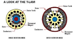
A 3-D view of a T-lam stator magnetic core structure reveals that instead of several one-piece laminations it contains multiple T-shaped laminations that are mechanically held together to obtain the individual core segments. In turn, each core segment is wound on a bobbin winder (typically a $25K machine). Then all these wound segments are assembled together to create the finished stator sub-assembly.
It is evident from a direct comparison that the concentrated T-lam winding has significantly less end turn length. Depending on core length, the ends turns in a solid core stator can amount to 30 to 60% of the total wire used to construct its distributed winding. This end-turn waste boosts the winding's electrical resistance by 30 to 60%.
In contrast, the end turns in a T-Lam motor typically amount to at most 7% of the total wire used to wind its concentrated winding. Thus the a T-Lam winding has much lower electrical resistance for the same number of total turns. Furthermore, the smaller volume of space taken up by end turns frees up room to make the core 3 to 5% longer. This lets rotor magnets be longer.
Moreover, slot fill ratios tend to be higher — Exlar normally gets 78 to 81% slot fill for all its T-lam stators versus 55 to 60% for its solid core stators. This higher slot fill generally allows T-lam stators to typically use thicker wire, about one wire gauge larger. Wire tables for copper magnet wire reveal that for every change in wire gauge, the wire's electrical resistance-per-foot changes by 26%. So a T-Lam motor having the same volume as its solid core counterpart, wound with the same number of turns, will have on average a winding resistance 40 to 45% lower.
To better understand the significance of lower winding resistance, consider the expression for the maximum continuous torque a BLDC servomotor can safely put out without overheating:
Where TR = rated winding temperature, °C; T0 = ambient temperature, °C; Rth = winding-to-ambient thermal resistance, °C/W; ω = motor angular velocity, radian/sec; DM = motor viscous damping, Nm/radian/sec; FM = motor friction, Nm; KT(TR) = motor total torque function at TR, Nm/A; R(TR) = winding electrical resistance at TR, Ω; TL(ω) = maximum continuous torque motor can deliver to its load at each velocity.
Next, consider the expression for the motor maximum continuous power output at each velocity, P(ω):
P(ω) = ωTL(ω)
(2)
Finally, consider the expression for the motor's percent power efficiency when the motor operates at its rated winding temperature:
The first point to notice in equations (1) (2) and (3) is that by lowering winding resistance and keeping all other parameter values fixed, a T-lam motor can put out more continuous torque and power for the same temperature rise. The T-lam architecture also improves the motor's power efficiency for a fixed motor power dissipation. The accompanying figures graphically show the affect of lowering winding resistance by 40%.
It is also clear that lowering winding resistance by 40% has another benefit. It lets the T-lam motor put out 17% higher continuous stall torque and power at a power efficiency that is 2% higher than that of a comparable solid core motor. (When both motors are operated with the same 130°C winding and 25°C ambient temperature and with no heat sink.)
Furthermore, the T-Lam is up to 5% more efficient than its solid-core equivalent when operated at less than its maximum allowable continuous torque-speed and power-speed curve. This is because the winding now operates at less than its 130°C rated temperature and the winding resistance is even lower.
Use of thermally conductive epoxy instead of varnish to impregnate the winding can also boost efficiency. For example, Exlar uses a potting epoxy that is a recognized component in a UL-1446 insulation system that has a Class 180 H (180°C) temperature rating. Actual measurement shows that potting the stator winding using this thermally conductive epoxy lowers its winding-to-ambient thermal resistance, Rth(°C/W), by 50% compared to impregnating the winding with a typical varnish.
Power output and efficiency curves make it clear that potting a T-lam stator with thermally conductive epoxy lowers the winding-to-ambient thermal resistance, Rth, by up to 50%. It also produces a motor that has 45% higher continuous stall torque and 63% higher maximum power output compared to the original solid core motor.
However, the power efficiency curve is somewhat counter intuitive. The potted SLM90-238 motor has about the same or slightly higher power efficiency between 0 and 8K rpm compared to the original solid core motor. As shown, above 8k rpm its efficiency rises above 8 rpm such that at 13 rpm its power efficiency is actually 10% higher than that of both a solid core and a T-lam motor impregnated with a varnish. Furthermore, between 13.3 and 15 rpm the potted version is infinitely more efficient. This is because a varnished motor's velocity-dependent power loss caused by both friction and viscous damping prevents the motor from producing continuous torque above 13.3K rpm without exceeding its 130°C rated winding temperature. Thus the question becomes: What prevents increased power efficiency when you pot the stator with thermally conductive epoxy and lower its thermal resistance by 50%?
To answer to this question one must look again at equations (1) and (3). Initially, the winding resistance for the T-lam motor is 40% lower compared to the original solid core design because of higher slot fill and less end turn waste. Hence, for each “I” amperes of current there is less I2R power loss. This lets the T-lam motor put out higher continuous torque and power with higher efficiency because the velocity dependent viscous damping and friction power loss remains basically the same for both types of motor.
Potting the T-lam motor with thermally conductive epoxy cuts in half the winding-to-ambient thermal resistance and boosts the maximum allowable power dissipation inside the motor by the same 50%. Because the winding's electrical resistance remains the same after it is potted, the increase in current needed to produce the higher torque and power results in higher I2R power loss. Thus the lower Rth does not boost power efficiency until the SLM90-238 gets above 11 rpm. The key to more power efficiency over the entire operating velocity range is to lower the winding electrical resistance. The only way to accomplish this is by operating the motor at a lower winding temperature.
The electrical resistance for copper magnet wire typically used to construct motor electrical winding depends on winding temperature. The accepted international standard for a copper winding's change in resistance with temperature is:
R(T) = R(T0) (1 + .00393(T-T0))
(4)
In equation (4), T0, is the reference temperature (typically 25°C) and T (°C) is the new winding temperature either above or below T0. Equation (1) shows that for a copper winding with an electrical resistance specified at 25°C, electrical resistance at 130°C rises by a factor of 1.4126 or 41%. However, if the winding operates at 100°C then the increase in resistance is only 1.294. This is 9% less than its 130°C value.
Suppose the SLM90-238 operated not at its maximum continuous torque-speed curve (dashed blue in the accompanying figure) but instead at a reduced level (solid red). It produces 17% higher continuous stall torque and maximum power output, compared to the original solid core motor but with the power efficiency (dashed Brown line). The reason: The winding temperature only rises to 100°C with a 25°C ambient because Rth is 50% lower. It takes less current to produce the lower torque and power, and there is 9% less winding resistance. Thus there is less I2R power lost to heat, so windings stay cooler and power efficiency rises.
More info
Exlar Corp - (www.exlar.com)
Proto-lams Corp - motor laminator, (www.protolam.com)
Thomson Laminations - motor laminator, (www.tlclam.net)
For a basic tutorial on PM motors, see R. Welch, “The Basics of Permanent Magnet Motor Operation,” available from Welch Enterprise ([email protected])
For information on the process of winding motors, refer to www.patentstorm.us/patents/4385435/description.html, www.alliance-winding.com/products/windinsert/index.html, odawara.com/products.htm, and www.alliance-winding.com/products/windinsert/autoassembly.html
For more information on motor thermal behavior, see R. Welch, “Continuous Dynamic and Intermittent Thermal Operation in Electric Motors,” a course offered by the SMMA Motor and Motion College (www.smma.org)
For more information on motor safe operating range, see R. Welch, “How to Measure a BLDC Servomotor's Safe Operating Area Curve (SOAC) Without Using a Dynamometer,” a tutorial available from Welch Enterprise ([email protected])
For more info on motor efficiency issues, see R. Welch, “How to Improve Electric Motor Power Efficiency,” a course offered by the SMMA Motor and Motion College (www.smma.org), and R. Welch, “How to Increase a Motor's Continuous Torque Output and Power Density By Potting its Stator with Thermally Conductive Epoxy,” Proceedings of the 2006 SMMA Fall Conference, Saint Louis, Mo.
About the Author
Comment About the Article
To join the conversation, and become an exclusive member of Electronic Design, create an account today!

Leaders relevant to this article: