Dimming techniques for LED drivers
ResourcesInternational Rectifier, www.irf.com |
The quest for energy efficiency has led manufacturers to investigate ways of dimming all kinds of lighting technologies, including those that usually can’t be dimmed. Consider, for example, fluorescent lamps. With relatively expensive dimmable electronic ballasts, fluorescent lamps can be dimmed to below 5% of maximum light output. But even with electronic ballasts, HID (high-intensity discharge) lamps cannot be dimmed to much more than half of their maximum light output. Dropping past that point risks experiencing noticeable color change and instability in their plasma arc.
To further complicate matters, most dimmable fluorescent and all HID systems are incompatible with standard triac-based phase dimmers. Instead, they use specialized dimming controllers, often demanding additional analog or digital dimming control cables.
Fluorescent and HID lamps are both types of arc discharge lamp. One reason they are so hard to dim is that the impedance of plasma arcs is non linear and varies considerably depending on current and temperature. In addition, there are operating points at which lamp impedance changes rapidly in response to small changes in arc current. This forces dimming circuitry to include a closed-loop current regulating system able to respond rapidly to such changes.
In contrast, it is much more straightforward to dim LEDs because of their makeup. LEDs consist of a solid state p-n junction with a fairly constant forward voltage drop. This constitutes a stable load that can be driven by a constant dc current source.
Off-line LED drivers are comprised of constant-current regulating switching power supplies generally equipped with dc outputs. LEDs, unlike discharge lamps, need no high-voltage ignition. So LED dimming can use pulse width modulation (PWM), in which the output current is switched on and off at a constant frequency with a variable duty cycle. This action adjusts the average current, which is proportional to the light output.
The PWM dimming frequency must be above 120 Hz to comply with Energy Star requirements by avoiding visible flicker. Alternatively, LEDs can be dimmed by reducing the dc current. However, this technique causes some white LEDs to change color and is more difficult to control at low dimming levels.
It is worth noting that the operating life of LED light sources depends on the operating temperature and current that the individual LED die see. Dimming reduces both of these parameters and thus potentially extends LED operating life.
Lumen maintenance for LEDs is specified by the L70 parameter, which indicates the average hours of operation until the light output deteriorates to 70% of its initial quantity. Either dimming technique described above will extend the L70 parameter by operating the LED at reduced output. One reason dimming capability is important for LED drivers is that the US Dept. of Energy has mandated such capability for any lamp hoping to gain an Energy Star rating.
Some early LED bulb replacement products are not dimmable. But legislation eliminating incandescent lights make it inevitable that dimmable LED products will eventually dominate the market.
There are several alternative approaches to dimming LEDs that apply in different segments of the market. LED-based replacements for incandescent or CFL lamps should be dimmable by standard wall dimmers. These are widely used and constitute the vast majority of all household dimmers. Wall dimmers use an extremely basic and cheap triac-based circuit originally designed to handle purely resistive incandescent light bulbs. (CFLs are capacitive, not resistive. Because they draw relatively little current from the ac line, they are fundamentally incompatible with triac-based dimmers.)
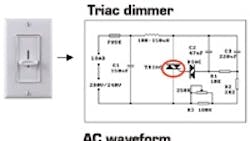
The triac is the switching element in the accompanying dimmer circuit. It fires at a certain point in the ac line cycle which can be adjusted by a potentiometer, allowing current to flow until the end of the cycle. The red waveform shows the ac line voltage at the dimmer input. The blue shows the phase cut voltage waveform coming out of the dimmer to the lamp.
The firing point of the triac determines the period of the ac line cycle over which the lamp gets current. In an incandescent lamp this would directly control the light level. But LEDs are driven by an ac-to-dc switching power supply, so dimming does not work in the same way. It is important to understand that the triac is turned on by a pulse and will continue to conduct until the current drops to a low level called the holding current, at which point it will switch off until fired again.
Continue on next page
The basic LED driver switching power supply circuit is not triac dimmable without some additional circuitry. Four techniques can be used to enable triac dimmer compatibility: a bleeder circuit, a charge pump, a simple PWM supply, and a complex PWM supply.
The bleeder circuit overcomes the problem caused by the use by LED drivers of a diode bridge and smoothing capacitor at the input. These elements do not provide a current to keep the triac on until the end of the ac line half cycle; current stops flowing after the input bus capacitor charges. If the triac switches off before the end of the cycle, the dimmer circuitry reenergizes it. This can happen several times in a cycle, causing flickering in the process. It can also possibly damage the LED driver components with high voltage transients and current surges.
The bleeder circuit is, in fact, a current source designed to draw a fixed current from the triac to keep it energized from the firing point to the end of the cycle even when the load draws no current. There are several implementations of the circuit. Some are designed to draw less current at the peak of the line voltage and more close to the zero crossing as a way to minimize the power loss. Although the bleeder technique does dissipate approximately a half watt, the efficiency and operating life advantages of LED lights far outweigh this loss.
The accompanying figure shows typical LED driver front end circuitry with a simple bleeder circuit. The bleeder circuit consists of a high-voltage MOSFET configured as a current source. A fixed voltage supplied to the gate, combined with a resistor from the source to 0 V, determine the bleed current. This current is typically set at 20 mA. This example includes a “passive valley fill” power factor correcting network.
The use of a charge pump is an alternative way to keep the triac switched on until the end of the cycle. Note the LED driver consists of a switching power supply oscillating around 50 to 100 kHz. A small portion of this high frequency can be coupled back to the line input through capacitors, thus maintaining a current in the triac. This technique can be effective but forces designers to take care not to introduce conducted EMI onto the ac line, which could violate EMC standards.
As described earlier, PWM is an effective method for controlling the brightness of LEDs by adjusting the average current. A simple PWM system for a triac-dimmable LED driver activates the LED output drive only during the time that the triac in the dimmer is switched on. The LED driver contains a dc bus storage capacitor, so it would normally be able to continue running on stored energy for much of the period when the triac is switched off. It would replenish during the “on” periods.
A simple circuit can be added to detect when the triac is on and to enable the LED output current drive only during this period. This lets the LEDs be dimmed as the dimmer is adjusted. This technique, however, cannot adjust brightness finely at low light levels, so advanced systems don’t use the triac firing angle information to directly drive the LED output.
Instead, the triac firing angle information is converted to a dc level that varies as the dimmer is adjusted up and down. This dc level is then compared with a dimming ramp waveform at a high frequency to eliminate flicker and shaped to provide the best possible linearity and range of dimming. The resulting comparison between these signals produces a PWM signal, which is used to pulse the LED driver output on and off and provide smooth dimming over a wide range.
Of course, use of circuitry for compatibility with standard dimmers does reduce efficiency somewhat. This is considered acceptable for low-power domestic applications. Industrial applications are another matter. There, LED dimming circuits are more likely to be designed from scratch.
Methods used for dimming whole fluorescent lighting systems in buildings can be equally well applied to LED-based systems. The typical approaches include analog 0-to-10-V dimming, digital addressable lighting interface (DALI) dimming, and power-line carrier.
All of the above systems basically network ballasts so they can be managed by central controllers. The controller in a 0-to-10-V system sends an analog signal that adjusts the ballast output according to the voltage on the control circuit. DALI, on the other hand, incorporates two-way communication. Each ballast has a separate address so the DALI controller can manage the output of each one individually. Finally, power-line-carrier techniques do much the same thing but use the ac power line to carry information back and forth between the controllers and light ballasts.
About the Author
Peter B. Green
(LED Group)
Comment About the Article
To join the conversation, and become an exclusive member of Electronic Design, create an account today!

Leaders relevant to this article: