Power Management, Chapter 1: Power Supply Fundamentals

This articles is part of the Power Management Series in the Power Management section of our Series Library.
Download this article as a .PDF eBook.
The key component of the dc power management system is the power supply that provides dc power for the associated system. The specific type of dc power management depends on its power input, which includes:
• AC input—A power supply that accepts an ac utility power input, rectifies and filters it, then applies the resulting dc voltage to a regulator circuit that provides a constant dc output voltage. There is a wide variety of ac-dc supplies that can have an output voltage from less than 1V to thousands of volts. This dc power management system usually employs a switch-mode power supply, although some linear supplies are available.
• DC input—A power supply that accepts a dc voltage input, typically 5 V, 12V, 24V, or 48 V and produces a dc output voltage. At the low end, a supply of this type can produce less than 1Vdc, whereas other dc-dc supplies can produce thousands of volts dc. Here, power management usually employs a switch-mode power supply.
• Battery input (for portable equipment)—Because of size and weight restrictions of portable equipment, this power management function is usually integrated with the rest of the electronic system. Some of these systems also include an ac adapter, which is a small power unit that plugs into the ac wall outlet and provides a dc output voltage. Usually, the ac adapter is used to power the unit and can also recharge the system battery.
• Ultralow voltage input (energy harvesting)—Energy harvesting can provide the power to charge, supplement, or replace batteries. A key component in energy harvesting is a power converter that can operate with ultralow voltage inputs. In operation, this power converter captures a minute amount of energy, accumulates it, stores it, and then maintains the stored energy as a power source. Low-voltage inputs can come from solar power, thermal energy, wind energy, or kinetic energy.
Linear vs. Switch-Mode Power Supplies
There are two basic power supply configurations used with dc power management subsystems: linear and switch-mode. Linear power supplies always conduct current. Switch-mode supplies convert dc to a switched signal that is then rectified to produce a dc output. Differences between these two configurations include size and weight, power-handling capability, EMI, and regulation.
The linear regulator’s main components are a pass transistor, error amplifier, and voltage reference, as seen in Fig. 1-1. The linear regulator maintains a constant output voltage by using the error amplifier to compare a portion of the output voltage with a stable voltage reference. If the output voltage tends to increase, feedback causes the pass transistor to lower the output voltage and vice versa. OEM linear supplies can handle several amperes of current. They are usually bulky benchtop or rack-mounted supplies.

In most applications, older, high-current linear supplies have been superseded by switch-mode supplies. Shown in Fig. 1-2 is a typical isolated switch-mode supply. Here, the ac input voltage is rectified and filtered to obtain a dc voltage for the other power-supply components. One widely used approach uses the on and off times pulse-width modulation (PWM) to control the power-switch output voltage. The ratio of on time to the switching period time is the duty cycle. The higher the duty cycle, the higher the power output from the power semiconductor switch.
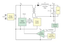
The error amp compares a portion of the output voltage feedback with a stable voltage reference to produce the drive for PWM circuit. The resulting drive for the PWM controls the duty cycle of the pulsed signal applied to the power switch, which in turn controls the power-supply dc output voltage. If the output voltage tends to rise or fall, the PWM changes the duty cycle so that the dc output voltage remains constant.
An isolation circuit is required to maintain isolation between the output ground and the power supplied to the power supply’s components. Usually, an optocoupler provides the isolation while permitting the feedback voltage to control the supply’s output.
The inductor-capacitor low-pass output filter converts the switched voltage from the switching transformer to a dc voltage. The filter is not perfect, so there is always some residual output noise called “ripple.” The amount of ripple depends on the effectiveness of the low-pass filter at the switching frequency. Power-supply switching frequencies can range between 100kHz to over 1MHz. Higher switching frequencies allow the use of smaller-size, lower-value inductors and capacitors in the output low-pass filter. However, higher frequencies can also increase power semiconductor losses, which reduces power-supply efficiency.
The power switch is a key component in the power supply in terms of power dissipation. The switch is usually a power MOSFET that operates in only two states—on and off. In the off state, the power switch draws very little current and dissipates very little power. In the on state, the power switch draws the maximum amount of current, but its on-resistance is low, so in most cases its power dissipation is minimal. In the transition from the on state to the off state and off to on, the power switch goes through its linear region so it can consume a moderate amount of power. The total losses for the power switch are therefore the sum of the on and off state plus the transition through its linear regions. The actual losses depend on the power switch and its operating characteristics. Table 1-1 compares the characteristics of isolated, ac-dc linear and switch-mode power supplies.
Read more articles from the Power Management Series in the Power Management section of our Series Library.

Voltage Regulator ICs
Regulating the output voltage of virtually all power supplies is dependent on voltage regulator ICs. These ICs obtain a DC input from rectified AC or a battery. In operation, the voltage regulator feeds back a percentage of its output voltage that is compared with a stable reference voltage. If the output voltage tends to rise or fall compared with the reference, the feedback causes the output to remain the same. Chapter 7 provides the details of voltage regulator ICs. Also, there are lab kits to help engineers understand voltage regulator IC operation.
Read more articles from the Power Management Series in the Power Management section of our Series Library.
Related Articles
3. Sam Davis, Digitally-Controlled AC-DC Supply, powerelectronics.com, January, 2012.
12. Sam Davis, Power Supply Characteristics FAQs, powerelectronics.com, April, 2014.
14. Power-Management Lab Kits for Young and Old Engineers
powerelectronics.com, July 13, 2016.

About the Author

Sam Davis
Sam Davis was the editor-in-chief of Power Electronics Technology magazine and website that is now part of Electronic Design. He has 18 years experience in electronic engineering design and management, six years in public relations and 25 years as a trade press editor. He holds a BSEE from Case-Western Reserve University, and did graduate work at the same school and UCLA. Sam was the editor for PCIM, the predecessor to Power Electronics Technology, from 1984 to 2004. His engineering experience includes circuit and system design for Litton Systems, Bunker-Ramo, Rocketdyne, and Clevite Corporation.. Design tasks included analog circuits, display systems, power supplies, underwater ordnance systems, and test systems. He also served as a program manager for a Litton Systems Navy program.
Sam is the author of Computer Data Displays, a book published by Prentice-Hall in the U.S. and Japan in 1969. He is also a recipient of the Jesse Neal Award for trade press editorial excellence, and has one patent for naval ship construction that simplifies electronic system integration.
You can also check out his Power Electronics blog.
Comment About the Article
To join the conversation, and become an exclusive member of Electronic Design, create an account today!

Leaders relevant to this article: