Power Management, Chapter 2: Power Supply Characteristics
This articles is part of the Power Management Series in the Power Management section of our Series Library.
Download this article as a .PDF eBook.
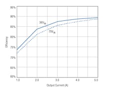
Efficiency is one of the most important power supply characteristics. It determines the thermal and electrical losses in the system, as well as the amount of cooling required. Also, it determines the physical package sizes of both the power supply and the final system. Plus, it determines the system component operating temperatures and the resultant system reliability. These factors contribute to the determination of the total system cost, both hardware and field support. Power-supply data sheets usually include a plot of efficiency versus output current, as shown in Fig. 2-1. This plot shows that efficiency varies with the power supply’s applied voltage as well as the output load current.
2-1. Typical efficiency plot for a power supply.
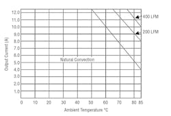
Efficiency, reliability, and operating temperature are interrelated. Power-supply data sheets usually include specific airflow and heat-sink requirements. For example, the ambient operating temperature affects the output load current that the power supply can handle reliably. Derating curves for the power supply (Fig. 2-2) indicate its reliable operating current versus temperature. Derating shows how much current the supply can be safely handle if it is operating with natural convection, or 200 LFM and 400 LFM.
2-2. Typical derating curves for a power supply.
Protecting the Supply
There are several other characteristics that impact power-supply operation. Among these are those employed to protect the supply, which are listed below.
Overcurrent: A failure mode caused by output load current that is greater than specified. It is limited by the maximum current capability of the power supply and controlled by internal protection circuits. It can also damage the power supply in some cases. Short circuits between the power-supply output and ground can create currents within the system that are limited only by the maximum current capability and internal impedance of the power supply. Without limiting, this high current can cause overheating and damage the power supply as well as the load and its interconnects (printed circuit board traces, cables). Therefore, most power supplies should have current limiting (overcurrent protection) that activates if the output current exceeds a specified maximum.
Overtemperature: A temperature that is above the power supply’s specified value must be prevented or it can cause power-supply failure. Excessive operating temperature can damage a power supply and the circuits connected to it. Therefore, many supplies employ a temperature sensor and associated circuits to disable the supply if its operating temperature exceeds a specific value. In particular, semiconductors used in the supply are vulnerable to temperatures beyond their specified limits. Many supplies include overtemperature protection that turns off the supply if the temperature exceeds the specified limit.
Overvoltage: This failure mode occurs if the output voltage goes above the specified dc value, which can impose excessive dc voltage that damages the load circuits. Typically, electronic system loads can withstand up to 20% overvoltage without incurring any permanent damage. If this is a consideration, select a supply that minimizes this risk. Many supplies include overvoltage protection that turns the supply off if the output voltage exceeds a specified amount. Another approach is a crowbar zener diode that conducts enough current at the overvoltage threshold so that it activates the power-supply current limiting and it shuts down.
Soft Start: Inrush current limitation may be needed when power is first applied or when new boards are hot plugged. Typically, this is achieved by a soft-start circuit that slows the initial rise of current and then allows normal operation. If left untreated, the inrush current can generate a high peak charging current that impacts the output voltage. If this is an important consideration, select a supply with this feature.
Undervoltage Lockout: Known as UVLO, it turns the supply on when it reaches a high enough input voltage and turns off the supply if the input voltage falls below a certain value. This feature is used for supplies operating from utility power as well as battery power. When operated from battery-based power UVLO disables the power supply (as well as the system) if the battery discharges so much that it drops supply’s input voltage too low to permit reliable operation.
Electromagnetic Compatibility (EMC): Involves design techniques that minimize electromagnetic interference (EMI). In switch-mode power supplies, a dc voltage is converted to a chopped or a pulsed waveform. This causes the power supply to generate narrow-band noise (EMI) at the fundamental of the switching frequency and its associated harmonics. To contain the noise, manufacturers must minimize radiated or conducted emissions.
Power-supply manufacturers minimize EMI radiation by enclosing the supply in a metal box or spray coating the case with a metallic material. Manufacturers also need to pay attention to the internal layout of the supply and the wiring that goes in and out of the supply, which can generate noise.
Most of the conducted interference on the power line is the result of the main switching transistor or output rectifiers. With power-factor correction and proper transformer design, connection of the heat sink, and filter design, the power-supply manufacturer can reduce conducted interference so that the supply can achieve EMI regulatory agency approvals without incurring excessive filter cost. Always check to see that the power-supply manufacturer meets the requirement of the regulatory EMI standards.
There are several power-supply characteristics that affect their operation:
Drift: The variation in dc output voltage as a function of time at constant line voltage, load, and ambient temperature.
Dynamic response: A power supply may be employed in a system where there is a requirement to provide fast dynamic response to a change in load power. That can be the case for the load of high-speed microprocessors with power-management functions. In this case, the microprocessor may be in a standby state and upon command it must start up or turn off immediately, which imposes high dynamic currents with fast ramp rates on the power supply. To accommodate the microprocessor, the supply’s output voltage must ramp up or down within a specified time interval, but without excessive overshoot.
Efficiency: Ratio of output-to-input power (in percent), measured at a given load current with nominal line conditions (Pout/Pin).
Holdup time: Time during which a power supply’s output voltage remains within specification following the loss of input power.
Inrush current: Peak instantaneous input current drawn by a power supply at turn-on.
International standards: Specify a power supply’s safety requirements and allowable EMI (electromagnetic interference) levels.
Isolation: Electrical separation between the input and output of a power supply measured in volts. A non-isolated has a dc path between the input and output of supply, whereas an isolated power supply employs a transformer to eliminate the dc path between input and output.
Line regulation: Change in value of dc output voltage resulting from a change in ac input voltage, specified as the change in ± mV or ± %.
Load regulation: Change in value of dc output voltage resulting from a change in load from open-circuit to maximum-rated output current, specified as the change in ± mV or ± %.
Output noise: This can occur in the power supply in the form of short bursts of high frequency energy. The noise is caused by charging and discharging of parasitic capacitances within the power supply during its operating cycle. Its amplitude is variable and can depend on the load impedance, external filtering, and how it is measurement.
Output voltage trim: Most power supplies have the ability to “trim” the output voltage, whose adjustment range does not need to be large, usually about ±10%. One common usage is to compensate for the dc distribution voltage drop within the system. Trimming can either be upward or downward from the nominal setting using an external resistor or potentiometer.
Periodic and random deviation (PARD): Unwanted periodic (ripple) or aperiodic (noise) deviation of the power-supply output voltage from its nominal value. PARD is expressed in mV peak-to-peak or rms, at a specified bandwidth.
Peak current: The maximum current that a power supply can provide for brief periods.
Peak power: The absolute maximum output power that a power supply can produce without damage. It is typically well beyond the continuous reliable output power capability and should only be used infrequently.
Power-supply sequencing: Sequential turn-on and off of power supplies may be required in systems with multiple operating voltages. That is, voltages must be applied in a specific sequence, otherwise the system can be damaged. For example, after applying the first voltage and it reaches a specific value, a second voltage can be ramped up, and so on. Sequencing works in reverse when power is removed, although speed is not usually as much of a problem as turn-on.
Remote on/off : This is preferred over switches to turn power supplies on and off. Power-supply data-sheet specifications usually detail the dc parameters for remote on/off, listing the on and off logic levels required.
Remote sense: A typical power supply monitors its output voltage and feeds a portion of it back to the supply to provide voltage regulation. In this way, if the output tends to rise or fall, the feedback regulates the supply’s output voltage. However, to maintain a constant output at the load, the power supply should actually monitor the voltage at the load. But, connections from a power supply’s output to its load have resistance and current flowing through them that produces a voltage drop that creates a voltage difference between the supply’s output and the actual load. For the optimal regulation, the voltage fed back to the power supply should be the actual load voltage. The supply’s two (plus and minus) remote sense connections monitor the actual load voltage, a portion of which is then fed back to the supply with very little voltage drop because the current through the two remote sense connections is very low. As a consequence, the voltage applied to the load is regulated.
Ripple: Rectifying and filtering a switching power supply’s output results in an ac component (ripple) that rides on its dc output. Ripple frequency is some integral multiple of the converter’s switching frequency, which depends on the converter topology. Ripple is relatively unaffected by load current, but can be decreased by external capacitor filtering.
Tracking: When using multiple output power supplies whereby one or more outputs follow another with changes in line, load, and temperature, so that each maintains the same proportional output voltage, within specified tracking tolerance, with respect to a common value.
PMBus
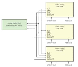
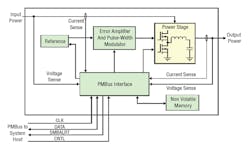
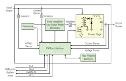
The PMBus specification describes the addition of digital control for a power supply over a specified physical bus, communications protocol, and command language. A conceptual diagram of PMBus-capable power supplies controlled from a central location is shown in Fig. 2-3. It contains a bus master and three slaves. Figures 2-4 and 2-5, respectively, show the block diagrams of typical non-isolated and isolated converters that might be found in the system shown in Fig. 2-3.
2-3. PMBus conceptual diagram.
2-4. Block diagram of typical non-isolated PMBus converter.
2-6. ISL8273M is compatible with PMBus Power System Management Protocol Specification Parts I and II version 1.2.
The SMBus device address is the only parameter that must be set by the external pins. All other device parameters can be set using PMBus commands.
The ISL8273M can operate without the PMBus in pin-strap mode with configurations programmed by pin-strap resistors, such as output voltage, switching frequency, device SMBus address, input UVLO, soft-start/stop, and current sharing.
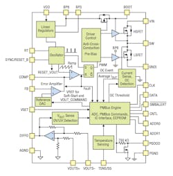
The TPS544x25 from Texas Instruments are PMBus 1.2 compliant, non-isolated synchronous buck converters with integrated FETs, capable of high-frequency operation and 20-A or 30-A from a 5 mm × 7 mm package (Fig. 2-7). High-frequency, low-loss switching, provided by an integrated NexFET power stage and optimized drivers, allows for very high-density power solutions. These devices implement the industry standard fixed-switching frequency, voltage-mode control with input feed-forward topology that responds instantly to input voltage change. These devices can be synchronized to the external clock to eliminate beat noise and reduce EMI/EMC.
2-7. TPS544C25 synchronous buck converter with PMBus and frequency synchronization.
The PMBus interface enables the Adaptive Voltage Scaling (AVS) through NexFET Power Stage VOUT_COMMAND, flexible converter configuration, as well as key parameter monitoring including output voltage, current, and an optional external temperature. Response to fault conditions can be set to either restart, latch-off, or ignore depending on system requirements. Two on-board linear regulators provide suitable power for the internal circuits.
Features
- Input voltage: 4.5V to 18V
- Output voltage: 0.5V to 5.5V
- Single thermal pad
- 500mV to 1500 mV reference for AVS and margining through PMBus
- 0.5% reference accuracy at 600mV and above
- Lossless low-side MOSFET current sensing
- Voltage mode control with input feed-forward
- Differential remote sensing
- Thermal shutdown
iJA Series
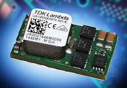
TDK-Lambda’s 35A iJA series of POL (point-of-load) non-isolated dc-dc converters are PMBus compliant and feature digital control (Fig. 2-8). These converters provide better dynamic performance and improved system stability, as well as allow a great deal of flexibility and customization to the end application’s needs.
2-8. TDK-Lambda’s 35A iJA series of POL non-isolated dc-dc converters are PMBus compliant.
The PMBus read-write functionality of the converter provides real-time, precision monitoring of voltage, current, and temperature, and allows full programmability of the iJA parameters. Function-setting pins make them easy to use in applications where PMBus communication is not implemented. A GUI (graphical user interface) and evaluation boards are available for development support.
Operating from an 8 to 14VDC input, the iJA series can provide output voltages from 0.6 to 3.3V, with a precision set-point accuracy of 1%. The series is designed to meet a wide range of applications, including servers, routers, and other Information & Communication Technology (ICT) equipment, semiconductor manufacturing equipment, measuring equipment, and general industrial equipment.
The surface-mount converters occupy only 0.45 square inch of board space, representing an ultra-high power density of 580 Watts per cubic inch. Overall dimensions are 22.9mm × 12.7mm × 9.7mm with a weight of just 6.5g. Optimization of components using digital control enables a high current output in high-temperature, low-airflow environments. The iJA power module has a typical efficiency of 94% with a 3.3V output, 12V input, and 80% loading.
Read more articles from the Power Management Series in the Power Management section of our Series Library.
Related Articles
2. Steve Sandler, How Can I Measure PSRR Using an Oscilloscope?, powerelectronics.com, August 2013.
3. Sam Davis, Back to Basics: Voltage Regulator ICs Part 1, powerelectronics.com, June 2013.
5. Tom Skopal, Power-Supply Failures Are Mostly Preventable, powerelectronics.com, August 2008.
About the Author

Sam Davis
Sam Davis was the editor-in-chief of Power Electronics Technology magazine and website that is now part of Electronic Design. He has 18 years experience in electronic engineering design and management, six years in public relations and 25 years as a trade press editor. He holds a BSEE from Case-Western Reserve University, and did graduate work at the same school and UCLA. Sam was the editor for PCIM, the predecessor to Power Electronics Technology, from 1984 to 2004. His engineering experience includes circuit and system design for Litton Systems, Bunker-Ramo, Rocketdyne, and Clevite Corporation.. Design tasks included analog circuits, display systems, power supplies, underwater ordnance systems, and test systems. He also served as a program manager for a Litton Systems Navy program.
Sam is the author of Computer Data Displays, a book published by Prentice-Hall in the U.S. and Japan in 1969. He is also a recipient of the Jesse Neal Award for trade press editorial excellence, and has one patent for naval ship construction that simplifies electronic system integration.
You can also check out his Power Electronics blog.

