The Loads Are Simulated, But the Connections are Real
During development of a battery-powered device, the flexibility that a variable power supply provides can be very useful. You can set the voltage to simulate a fully charged or partially discharged battery, and some supplies also have variable output resistance to more completely model a battery’s performance. Working with a suitable power supply is much more convenient and productive than actually having to rely on a set of batteries in various states of charge. It’s also far safer because a power supply’s output current can be limited to a maximum value.
In a similar way, with an electronic load you can explore the effect of load variations on a particular source. For example, there are many loads that demand rapid changes in supply voltage or current. Adrian Roche, a design engineer at IntePro Systems, said that the company recently developed the EL 2000 HS electronic load featuring rise times faster than 1 µs to test point-of-load (POL) and point-of-use (POU) DC-to-DC converters.
The 40-W load features 0 to 20-VDC and 0 to 20-A ratings, and multiple loads can be paralleled for higher power applications. All control is by a LAN connection with 500-V isolation. For the EL 2000 HS, the emphasis is on speed with a 40-A/µs rise time.
To match the high rate of change, the load has a 50-MHz measurement bandwidth with a 150-MS/s, 14-bit digitizer. Measurements include volts, current, power, noise, settling time, and overshoot/undershoot for both V and I.
In today’s electronic systems that may use several different and tightly controlled voltages, it is common practice to distribute a higher voltage bus and locally use separate DC-to-DC converters as required. These POL/POU converters must have sufficiently fast transient performance that the load, not the converter, determines the rate of change of current.
One way to test converters is to simulate the real load with a high-speed electronic load. Rather than only determining that the converter did or did not support the load’s rate of current change, you can find the maximum rate that it provides. Conversely, electronic loads with a separate soft-start function and/or programmable current slew rates allow you to avoid abnormal operating conditions if the actual load has a soft-start capability.
As Figure 1 shows, the operating area for an electronic load is bounded by the minimum input voltage necessary to maintain control, a resistive portion that increases with current to the maximum current rating, a maximum power portion, and a maximum voltage limit. All DC loads are similarly constrained although specific design features will alter the shape of the graph.
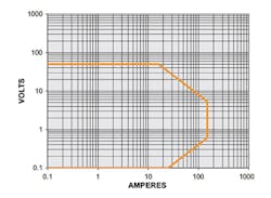
Courtesy of Astrodyne TDI
Operating modes
Most DC electronic loads have four basic operating modes: constant voltage (CV), constant power (CP), constant current (CC), and constant resistance (CR). CR, as the name implies, is equivalent to using a fixed-resistance load—the voltage linearly increases with current. The CV setting simulates a battery being charged. The load will adjust its resistance to sink more or less current while keeping the terminal voltage constant.
The CP characteristic has a hyperbolic shape with current reducing as voltage increases and vice-versa. Switching between two or more values of CC tests a source’s load regulation—how well does a power supply maintain its terminal voltage when the load current is changed?
GW Instek’s PEL-3000 Series features three additional modes that combine CV with CC, CP, or CR. The “+CV” modes basically provide additional test safety. For example, the CC+CV mode could be used to test a power supply at a fixed output voltage. The load could require more and more current from a supply until the supply’s maximum output current was exceeded. At that point, the supply would switch to CC and the load to CV. According to the PEL-3000 Series datasheet, this action protects the supply under test—the load shuts down once the supply voltage is lower than the +CV set voltage.
Chroma Systems Solutions’ 63200A and 63600 DC loads use high-speed 16-bit DSPs to enhance capabilities such as programmable slew rates, programmable transients, and added user-defined waveforms. Several modules in the 63600 Series are shown together with the 63600-5 five-slot mainframe in Figure 2. The company’s Larry Sharp, senior applications engineer, explained, “Chroma’s loads can produce dynamic load transients with fast slew rates and can create sine wave current on top of a DC current up to 50 kHz…. They also have up to 255 internally stored programmable load sequences that can be set to dwell times from 100 µs to 30 s, repeated continuously, or with counts up to 9,999 times.”
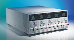
Courtesy of Chroma Systems Solutions
A press release describes some of the 63200A’s capabilities in more detail. A smart master/slave mode control supports programming the total load currents to the master where individual load currents are calculated and downloaded to the slave loads. This facility simplifies operation when using several loads in parallel to emulate a single high-power load.
The 63200A loads can be synchronously paralleled to a total of 480 kW and dynamically synchronized for generating complex multichannel transient profiles. A 300% peak overpower capacity provides extra headroom for fault-condition simulations in automotive battery and fuel cell tests.
Typical 63200A applications include testing a wide range of power conversion products such as AC/DC and server power supplies, DC/DC converters, EV batteries, and automotive charging stations.
The 63200A and 63600 families of DC loads measure voltage, current, power, time, and ±voltage peak. You can select measurement sample rates from 25 S/s to 500 kS/s, and software is available to capture and view voltage and current transient responses. In addition, there are advanced measurements for maximum power point tracking (MPPT) for testing solar arrays and Ahr and Whr measurements for testing battery discharge. Cut-off voltage and time (up to 100,000 s) can be set to ensure that battery discharge testing ends before the battery is damaged by overdischarge.
Herman vanEijkelenburg, director of marketing at Adaptive Power Systems (APS), said, “APS loads also support some unique measurement modes such as the MPPT of PV panels when loaded with an APS DC load. Other built-in test and measurement features are short, over-current protection, and over-power protection modes where load settings and measurements are sequenced and used to quickly determine EUT pass or fail based on user-set measurement criteria.
“To support EV and HEV battery development and testing to high power levels,” he continued, “the APS 5VP Series has built-in battery charge and discharge test profiles and monitoring that eliminate the need to write customer test programs. And, for real-time current acquisition, all APS electronic loads—both AC and DC—provide current monitor outputs which allow the use of a storage scope to capture real-time current waveforms.”
B&K Precision’s 8600 Series DC loads offer several special features, according to the company’s James Schada, senior product marketing manager. He said, “CR-LED mode allows users to simulate a load profile designed for LED driver testing applications. This mode operates in constant resistance with the additional capability for user-defined parameters that emulate the V-I characteristics of typical LEDs to apply as the input load.
“The built-in battery test function of the 8600 Series … uses various computational algorithms to simplify common battery load tests. This allows the user to perform CC discharge tests with three different stop condition options: cut-off voltage, capacity, or time.” He concluded, “The load will compute real-time capacity data based on input measurements while discharging the battery under test.”
For many applications, an electronic load’s built-in remote sense capability can be useful. Schada confirmed that all of B&K’s loads provide remote sensing terminals to compensate for the voltage drop across the test leads at high current. He explained that the voltage will be measured at the source and that value used to alter the load settings. For example, he said, “It will compensate for the voltage drop [of the source-to-load wiring] and adjust the load current accordingly in constant power mode.”
A note in an Ametek document adds, “In remote sense operation, the electronic load senses the input at output terminals of the source. … the remote sense terminals of the load are connected to the output of the source. Remote sensing compensates for the voltage drop in applications that require long leads. It is useful in any operating mode requiring accurate voltage read back. Load leads should be bundled or tied together to minimize inductance.”1
Connecting to a load
Determining the best way to connect to a load is closely related to the load selection process. If you need to test sources that output hundreds of amps and/or volts, you need a load with adequate ratings. One value that can easily be overlooked is the lowest voltage that a load can support at a given current.
The load’s internal regulation circuits have a lower limit on the input signal they require—often about 0.1 V—and the load itself has a finite minimum resistance. If you need to work at low voltages and high currents, the voltage drop across the cables connecting the source to the load becomes very important. As shown in Figure 3, one way to minimize this drop is to use large solid copper busbars. In the figure, several loads are used in parallel to further lower the minimum load resistance and increase the maximum current rating.

Courtesy of GW Instek
The achievable low-voltage/high-current combination for many loads has been improved by the availability of MOSFETs with lower linear-region source-to-drain resistance (Rds (on)). As described by Chroma’s Larry Sharp, “New developments in power MOSFETs designed to operate with a lower Rds (on) … allow our electronic loads to continue to operate at lower voltages without saturating the transistors and continue to control the load currents accurately. By utilizing the latest in power MOSFETs, Chroma’s new 63200A and 63600 families of electronic DC loads have been developed for low-voltage applications, below 1 V without the need for an additional bias power supply, and still have the capability to operate at higher voltages and current levels up to 1,200 V and 1,000 A.”
For true zero-volt operation, a DC bias power supply must be inserted between the source being tested and the load. As the name implies, the additional supply “biases” the load so that very low voltage sources can be accommodated. Some loads, such as Amrel’s ZVL Series of DC loads or Kikusui America’s PLZ164/664WA, include a bias supply.
A load’s remote sense circuitry typically can accommodate 1 or 2 V of drop across the connecting cables. For a steady-state or slowly changing high-current output, keeping the wiring resistance low is the main requirement. For transient tests, both the wiring resistance and inductance must be low. A high-inductance connection not only slows down the rate of change of current that is sensed by the load, but it also increases the remotely sensed voltage.
Several things contribute to wiring inductance, but the area of the loop formed by the source output and return cables is the largest contributor. This is the reason that the Ametek reference suggests tying load leads together to minimize inductance.
For two parallel wires
L = 10.16ln(2H/Deff) in nH/inch
C = 1.412εr /ln(2H/D) in pF/inch
where: H = wire separation in inches
D = wire diameter in inches
Deff = effective diameter to include self inductance
εr = relative dielectric constant
Setting the effective wire diameter to 0.7788 x the actual diameter takes into account the two-wire circuit’s internal inductance. For two 3-foot long wires 0.1 inches in diameter, separated by 1 inch, the inductance is about 1.2 µH. Reducing the spacing to 0.25 inch lowers the inductance to about 0.68 µH.
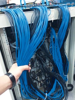
Courtesy of GW Instek
GW Instek’s Yuanyu Tseng, design engineer at the company’s Power Business unit, said, “Problems with wire inductance are overcome by increasing the total wire count to the DUT. This is true in server power testing where higher slew rates, lower voltage, and high current are demanded.” Figure 4 shows this type of test setup. Twenty paths reduce the overall inductance to 5% of a single loop’s value—about 60 nH for 3-foot wires with a 1-inch separation.
However, as the equations show, capacitance varies as the inverse of the log() term, so changing the spacing-to-diameter ratio to reduce inductance increases capacitance as does providing lots of parallel paths. For the same two-wire example, the capacitance for a single pair is about 22 pF, assuming a value of 1.3 for εr to account for some insulation. Twenty pairs would have a total capacitance around 440 pF.
The loop area is neatly avoided in coaxial cables. For coaxial cables
L = 0.140μrlog(b/a) in μH/foot
where µr = relative permeability—about 1.0 for nonmagnetic materials like wire insulation.
C = 7.3644εr/log(b/a) in pF/foot
where: b = outer conductor inner radius (inches)
a = inner conductor radius
For a 3-foot length of coaxial cable with a 0.1-inch diameter center conductor and 0.3-inch outer diameter with εr = 2.2, the inductance is 0.2 µH and the capacitance 100 pF. As with the equations for parallel wires, the coaxial cable equations clearly show the same inverse relationship: reducing inductance by lowering the b/a ratio increases capacitance.
Interestingly, Temp-Flex Cable, a Molex company, makes what it calls a low-inductance, high-current cable that takes advantage of the b/a relationship (Figure 5). The inner conductor diameter and that of the outer cylindrical conductor are almost the same, the two being separated by a thin insulating layer. The result is a truly minimal inductance cable. Using the same 3-foot example, if the inner conductor diameter is increased to 0.24 inch and the outer conductor left at 0.3 inch, the inductance reduces to about 0.04 µH, but the capacitance increases to 500 pF. Temp-Flex states that the inductance per foot typically is 0.02 µH for the company’s cable.
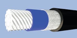
Courtesy of Temp-Flex
The best wiring approach depends very much on the application. Servers demand fast changes to supply current, so inductance is more critical than capacitance. And, as Figure 4 shows, simple wiring techniques can provide both low inductance and high current while holding the overall capacitance to a reasonable level. The Temp-Flex cable is a special item not commonly found in a test department. It may not be as well suited to a server’s mating connector as multiple wires. Nevertheless, it does show what’s possible in a cable if extremely low inductance is needed.
Finally, laminated busbars are an approach that has become popular in switching power applications such as those involving IGBTs. The inductance of wide conductors separated by a thin insulating layer can be very small. However, as the insulating layer is reduced in thickness, the capacitance increases. Still, when large fast current changes are involved, low inductance usually is the dominant requirement. The effect of added capacitance isn’t as important.
Keeping cool
By definition, loads absorb power, so one distinction among loads is the amount of power that can be handled. As Figure 3 shows, numerous fans provide air cooling in many models. Chroma’s Sharp listed the company’s use of thermal flowing technology as key to achieving a 6-kW load in a 4U enclosure.
In addition to air-cooled loads, Astrodyne TDI makes the XBL GEN2 Liquid Series of water-cooled DC loads. The high power density allows up to 120-kW in a single 63-inch high 19-inch rack, complete with all plumbing, servos, and relays. In addition, the loads in a rack system are interconnected via copper-plate busing to minimize inductance and capacitance. Ametek’s AMREL brand PLW Series loads also are water cooled.
Regeneration, in which power is converted to the local AC power frequency and returned to the mains supply, is yet another way to deal with dissipation. Kikusui makes the PLZ6000R regenerative 6-kW DC load. This feature is less common in lower power DC loads although often found in very high-power DC loads such as AeroVironment’s 250-kW AV-900/900 CE. IntePro offers the regenerative single-channel ELR 9000 DC load with up to 10.5 kW capacity in a single chassis and the multichannel regenerative ELR-5000 with up to 3.5 kW in a 10-channel chassis.
AC loads also are available, and many offer regenerative power recovery. Examples include PREEN AC Power’s 60-kVA PEL Series regenerative AC load bank, NH Research’s Model 9410 AC and DC regenerative load with power ratings from 12 kW to 96 kW, and Ametek’s California Instruments brand 3091LD Series 3-kVA AC load.
Reference
- PLA/PLW Series Programmable DC Electronic Load, Operating Manual, Ametek Programmable Power, M470039-01 REV B, October 2015.
For more information
About the Author

Tom Lecklider
Comment About the Article
To join the conversation, and become an exclusive member of Electronic Design, create an account today!

Leaders relevant to this article: