2,300-V SiC Power Module Raises the Bar for Renewable Energy
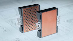
Wolfspeed is bringing the power-handling properties of silicon carbide (SiC) to the renewable energy, energy storage, and high-capacity EV fast-charging sectors with its new family of 2,300-V power modules.
Joining the company’s WolfPack family, the baseplate-less SiC power modules are well-suited for the 1,500-V DC bus prevalent in utility-scale inverters and energy storage that connect to renewable-powered grids. One of the most valuable properties of SiC is that it can safely and reliably handle higher voltages than silicon and dissipate heat more efficiently, giving it the advantage when regulating power in renewable energy systems.
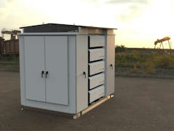
Wolfspeed partnered with EPC Power to integrate the module in a new class of inverter called “M.” It fuses the flexibility and reliability of string-style inverters typically seen in residential and commercial solar systems with the capacity of more traditional “central” inverters to handle up to thousands of kilowatts efficiently, safely, and reliably.
The new M is designed for storing solar, wind, and other forms of renewable energy in large-scale batteries and then drawing it out at times of high demand to stabilize the electric grid.
Traditionally, energy storage systems use a central inverter to convert a DC input voltage into AC voltages of the desired frequency and waveform used by electric grids. These monolithic units manage up to hundreds of thousands of watts, and they’re prone to downtime due to their size and complexity. These inverters can be taxed further when storing large loads of renewable energy for extended periods of time, said Wolfspeed.
>>Check out this TechXchange and the Library Series for similar articles and videos
SiC power devices such as Wolfspeed’s “open the door to a step-change in inverter performance and reliability,” said Devin Dilley, president and chief product officer of EPC.
Flipping the Switch: SiC Shoots for Higher Power Efficiency
The new modules tap the faster switching speeds and other characteristics of SiC to improve system efficiency.
They deliver a 77% reduction in switching losses over the silicon IGBTs that have dominated the power landscape for decades. They can also achieve up to a 3X reduction in switching losses compared to other SiC power devices intended for the 1,500-V DC bus, along with 15% greater voltage headroom than SiC power modules in the same class. Wolfspeed also touted improved dynamic performance with consistent temperature stability.
Since SiC power MOSFETs have faster turn-on and turn-off speeds than IGBTs, they can reduce the number of capacitors, inductors, and other passives in the system. Wolfspeed said the SiC MOSFETs in the 2,300-V module also help reduce the footprint of the EMI filters. The new WolfPack family features half-bridge, six-pack, and full-bridge configurations all with the option of pre-applied thermal interface materials.
One of its more distinctive features is the removal of the baseplate mounted to the underbelly of most other power modules. In most cases, IGBTs or SiC power FETs are soldered to a substrate that can handle high currents and provide high-voltage isolation up to several thousand volts across a wide temperature range. Many of the most widely used power substrates use direct copper bonding (DBC) thanks to its high thermal conductivity. In general, they consist of a ceramic tile with a sheet of copper bonded to one or both sides.
The substrates populated by power FETs can then be soldered to a rectangular baseplate. The baseplate is used to create optimal contact with the heatsink so that harsh temperatures can be mitigated before they take a toll on the system's efficiency and reliability. This is standard practice in heavy-duty power electronics, where several substrates must be placed on one large baseplate so they can all reliably contact the heatsink. These baseplates are rarely used in low- to medium-power modules that require a single substrate.
Wolfspeed’s new device also has higher durability, with its improved failure-in-time (FIT) rate for continuous 1,500-V DC operation and higher resistance to cosmic-radiation-related failures compared to 2,000-V modules.
SiC Bridges the Gap Between Two- and Three-Level Inverters
EPC leverages the faster switching frequencies and other characteristics of SiC in the M inverter, which is what it dubbed the first utility-scale, string-style inverter optimized for battery-based energy storage systems.
EPC said it used the 2,300-V SiC power device to drastically scale down the system, reducing the number of passive components inside it. According to the company, SiC also made it possible to use a two-level topology, reducing the complexity and cost of more traditional three-level inverters based on IGBTs. The M is not only smaller and less costly, but it’s also highly modular. That means several units can be strapped together into customized central-style inverters that output the three-phase AC voltage. The inverters are also easier to install and maintain.
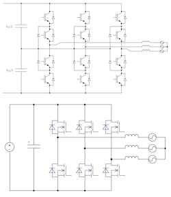
In general, a two-level inverter is comprised of three power stages, each with a pair of power FETs placed in parallel with a diode connected to a large-scale battery pack or other DC voltage source and the AC load. In the case of energy storage systems, the two-level inverter can produce AC outputs with a frequency and waveform used by the grid or other power-distribution systems by turning power switches on and off at high frequencies. The switches are turned on and off rapidly by the MCU or CPU that puts out pulse-width-modulation (PWM) signals.
These two-level inverters are frequently used in home appliances and a wide array of other low-power applications. In contrast, three-level inverters tend to be a better fit for heavy-duty power systems in industrial motors, EVs, and solar, wind, and other renewable energy systems that must translate increasingly high DC voltages to AC.
The three-level topology—also called the neutral point clamped (NPC) architecture—is based on three power stages. Each “leg” contains four power transistors—in most cases, IGBTs—placed in a half-bridge configuration. While the two-level inverter is able to output waveforms that switch between positive and negative voltage, the presence of these three power stages can produce three voltage levels: positive (+Vdc), negative (−Vdc), and zero (0 V).
With its additional voltage level, the NPC can generate a more sinusoidal output voltage with less harmonic distortion. The smoother output waveform gives it higher efficiency, which makes more of a difference when handling larger amounts of power. It’s also ideal for electric motors at the heart of modern EVs that run on three-phase AC.
Moreover, the cleaner output effectively increases the system’s switching frequency, making it possible to use smaller capacitors and magnetics to reduce ripples in the output. That ultimately reduces costs.
The two-level inverter requires a higher switching frequency than a three-level inverter to produce the same output waveform. Thanks to its limited output voltage levels—typically +Vdc and −Vdc—the two-level topology produces more of a square, staircase-like output waveform with higher harmonic distortion, limiting its efficiency.
The three-level topology also uses a pair of large bus capacitors to split the DC voltage in half before sending it into the power transistors. The other purpose of these DC Link capacitors is to smooth out the DC voltages traveling the power rails and remove the ripple caused by the rapid switching of the IGBTs or MOSFETs in the power supply. The inverter “clamps” the voltage at half the DC bus voltage, also called the neutral point.
Since every power transistor in the three-level topology handles half of DC bus voltage, power devices with half the withstand voltage may be employed, which will inevitably improve efficiency. Compare that to a two-level inverter, where each device must be able to withstand the full DC bus voltage. In general, IGBTs and other power FETs have higher switching power losses as voltage climbs. These devices must be made physically larger to handle higher voltages—and the larger the power transistor, the more on-resistance (RDS(on)).
One of the advantages of SiC is its higher breakdown voltage, which means it can handle the same voltages as silicon in a smaller space. As a result, SiC power MOSFETs reduce switching losses compared to IGBTs.
SiC Makes a Material Difference in Power Electronics
Though they can handle high voltages more efficiently, three-level inverters are also more complex, requiring a larger number of power switches and the gate drivers to control them. These additional components increase costs as well.
EPC is leveraging the higher voltage and faster switching speeds of the 2,300-V SiC modules to bridge the gaps between these power architectures. This significantly reduces costs by moving the system’s design from a legacy busbar to more affordable printed circuit boards (PCBs), while reducing the gate-driver count and control complexity surrounding the power FETs, Wolfspeed said. In addition, the system-level cost savings can help balance out the higher price tag for SiC power devices compared to IGBTs.
While it already has higher durability, the Wolfspeed module also reduces the number of potential single points of failure in the system when used in two-level topologies, giving the M a longer lifetime and higher reliability.
>>Check out this TechXchange and the Library Series for similar articles and videos
About the Author
James Morra
Senior Editor
James Morra is the senior editor for Electronic Design, covering the semiconductor industry and new technology trends, with a focus on power electronics and power management. He also reports on the business behind electrical engineering, including the electronics supply chain. He joined Electronic Design in 2015 and is based in Chicago, Illinois.


