From 48 V to 800 V: The Hard Challenges for High-Voltage DC Power in Data Centers

What you'll learn:
- The evolution of power delivery in data centers.
- The design challenges for high-voltage DC power in data centers.
- Isolation: How to handle it in high-voltage DC power systems.
- Power topologies: Balancing cost, speed, efficiency, and isolation.
Data centers—specifically those driving the latest innovations in AI—are consuming more and more power. Current research from Goldman Sachs shows that data centers devour 2% of all global electricity today, with expectations for that number to increase to 10% by 2030.
This exposes the shortcoming of traditional power electronics in data centers, from the power-distribution systems supplying AC to columns of servers, to voltage regulators feeding DC power, to the high-performance AI chips at the heart of it all. The data center’s power architecture must undergo major changes to deal with rising power demands of AI, and, in turn, electronic designers will have to solve a number of challenges.
This article is part of this special report:

Generational Divide: The Evolution of Power Delivery in Data Centers
To understand where things are headed in terms of power in data centers, it’s important to understand the construction of power architectures now. Figure 1 shows the main building blocks of what you could call a “first-generation” power architecture. In this scenario, three-phase AC (typically a 480-V line-to-line voltage) comes into the data center and feeds an uninterruptible power supply (UPS). The UPS enables battery backup and helps provide a stable AC voltage to the server rack. Inside the server rack, that AC voltage is rectified and stepped down to 12 V using common redundant power supplies in each server blade.
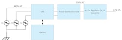
This architecture has been the industry standard for data-center power delivery for decades, and a large portion of systems today still have this configuration. A typical server rack in this type of architecture will support power ranging from 10 to 15 kW.
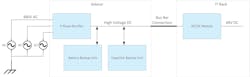
About a decade ago, the technology industry at large started pushing for higher efficiency in data centers. The rise of colossal cloud data centers contributed to increased power levels, which led to the “second-generation” architecture (Fig. 2).

This new system has several differences to the first generation. The output voltage of server power supplies increased to 48 V, along with the consolidation of power supplies into power shelves, also called “open rack” power supplies. A local battery backup unit is incorporated into the rack as well.
All these improvements lead to a 5% increase in the efficiency of power-conversion stages, while increasing the amount of deliverable power. In a cloud computing data center, the typical rack will have 40 kW to over 100 kW of power.
But as power-hungry AI chips come to dominate data centers, the second-generation architecture is reaching its physical limits. The power demands of AI data centers are climbing up to 600 kW to 1 MW in a single rack. Today, AI workloads require an immense amount of computing, which necessitates reducing the distance of the physical connections between the graphic processing units (GPUs), the central processing unit (CPU), and networking switches. This configuration means that big and bulky power supplies need to move out of the IT rack.
That’s why the third-generation architecture introduced the concept of a sidecar, which is basically a separate rack just for power connected to the server rack over a busbar connection (Fig. 3).
The Design Challenges for High-Voltage DC Power in Data Centers
Now that we’ve reviewed where the data center of the future is headed, we can discuss the challenges for high-voltage DC power distribution and some potential solutions. Power designers and systems engineers have a long list of questions they need to ask themselves—some of which we may not have even considered yet. But here are several to focus on:
- What is the optimal output voltage level? +400 V, +800 V, ±400 V?
- What is the role of isolation in the system? Is it strictly necessary on the high-voltage output?
- What are the right power-conversion topologies for the sidecar? What about in the server rack?
If the main motivation for moving the power supplies out of the IT rack is to increase the computing density, why do you have to change the output voltage of the power supplies? The simple answer is related to the busbars that carry the power from the sidecar to the IT rack. If the server rack requires 600 kW of power to run computationally heavy workloads such as AI training and inferencing, it would take 12,500 A of current (not considering any transmission losses) to deliver that power at 48 V.
Because of the current density that’s needed, the physical size of that busbar would be very large and weigh close to 200 pounds. These busbars would also require liquid cooling, increasing cost and complexity. Conversely, if you increased the power-distribution voltage to 800 V DC, you would need only 750 A for a 600-kW rack. This current level would allow for air cooling and a weight reduction of 85% per busbar.
The power-distribution voltage must increase—that much is clear. But what is the right voltage level? The +400-, +800-, or ±400-V levels are already used in today’s electric vehicles (EVs) and the associated charging infrastructure.
The +400-V voltage makes a lot of sense because it’s already widely used in today’s data centers: The power-factor-correction (PFC) stage in most single-phase AC-DC power supplies outputs +400 V before the LLC stage steps it down to 48 V or 12 V, and electrical components are readily available for use. Engineers also have a solid understanding of 400 V from a safety perspective, as well as regarding creepage and clearance spacing in designs. But if the power levels increase more, the busbars could become a problem.
The +800-V level is another viable option for the bus voltage, as it will allow for smaller busbars and higher power-distribution efficiency. This is a relatively new ecosystem for components, though. Engineers will have to work through a range of technical questions regarding safety and spacing. A third option would be to combine the first two options and choose ±400 V. Its main drawback is that this voltage requires complex control to ensure balanced loads.
Isolation: How to Handle It in High-Voltage DC Power Systems
It’s important to consider all three voltage options, but another issue will influence your choice: isolation.
Isolation and insulation have two purposes: one is end-user safety, and the other is to keep the ground loops separated. Both are very important for data-center architectures. Because of the power levels needed, it makes sense to have multiple smaller power supplies in parallel, making sure that these power supplies share current.
Figure 4 illustrates several options for the output voltages and isolation schemes. The first option is the most straightforward one, as it involves turning the PFC stage into a separate power supply unit (PSU). Despite its advantages, there’s uncertainty on whether companies will accept it. There are also issues around current sharing and balancing when paralleling multiple non-isolated AC-DC power supplies. Compared to other options with an additional isolation stage, this first option offers the highest efficiency and lowest cost.
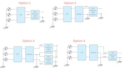
The second, third, and fourth options introduce isolation after the AC-DC stage to address current balancing. The third and fourth options use a split rail to generate ±400 V, with the main difference being the number of busbars required (three versus two). The fourth option needs some additional control to ensure balanced loads on the ±400 V.
Power Topologies: Balancing Cost, Speed, Efficiency, and Isolation
Another decision involves what topology to use for the AC-DC rectifier. Many factors drive the topology choice, including cost, efficiency, transients on the load, and isolation.
A two-stage approach, where one stage handles the rectifier and a separate stage manages the isolation, is the most traditional and popular way to design a power system. There are many well-known topologies, such as the Vienna rectifier, T-type inverter, or active neutral point clamp, for the rectifier.
Similarly, isolated DC-DC stages, such as three-phase LLC or full-bridge LLC, are available to achieve regulation and isolation. One of the big advantages of this approach is the ability to easily handle energy storage for transients and line-dropout events by adding extra capacitance between the rectifier and isolated DC-DC stage.
Another potential approach is to use a single stage to handle both AC-DC rectification and isolation. This is also known as a matrix converter. Figure 5 presents a simplified schematic for a single-stage matrix converter.
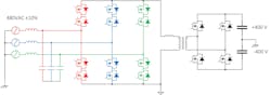
This type of converter can drive efficiency benefits by reducing the number of switches in the conduction path and by shrinking the overall number of switches and magnetics, thus lowering costs. Some potential drawbacks crop up when it comes to energy storage, though, in addition to concerns about surge voltages.
The matrix converter is also a perfect application for bidirectional switches to help reduce costs and improve efficiency even more. Still, a number of questions and technical details must be figured out to implement this type of design.
The shift to high-voltage DC power distribution is bound to bring about many changes to data-center power supplies. The opportunity to solve complex issues and improve the power supplies is happening now. To meet the power demands of new processors, the data centers of tomorrow will rely on decisions made today.
Read more articles from this special report

About the Author

Robert Taylor
Sector GM, Power Design Services and Power Delivery, Texas Instruments
Robert Taylor is Sector GM for Power Design Services and Power Delivery at Texas Instruments.

Sean Yu
Systems Manager, Power Design Services and Power Delivery, Texas Instruments
Sean Yu is Systems Manager for Power Design Services and Power Delivery at Texas Instruments.
Comment About the Article
To join the conversation, and become an exclusive member of Electronic Design, create an account today!

Leaders relevant to this article: