Battery-Management IC Uses EIS to Monitor Cells Inside and Out
What you’ll learn:
- How electrochemical impedance spectroscopy (EIS) gives battery-management systems deeper insight into individual battery cells.
- How cell impedance readings can improve state-of-charge estimation and provide earlier indications of cell degradation.
- How TI is integrating EIS into battery-management hardware for electric vehicles and energy storage systems.
A battery-management system (BMS) oversees everything about a battery pack, continuously monitoring it to maximize runtime, reliability, and safety. However, even the most advanced designs today have blind spots. The cell voltages, pack current, and a limited number of temperature sensors tend to be the only accessible signals at the pack level. They effectively measure the cells from the outside, presenting a relatively coarse picture of the battery pack’s condition. The electrochemical processes unfolding inside each cell remain largely hidden.
Texas Instruments is one of the vendors bringing electrochemical impedance spectroscopy (EIS) directly into the BMS, giving it the ability to look inside cells. The EIS engine inside its new BQ79826Z-Q1 stackable battery monitor can measure the impedance of each cell in real-time.
By detecting subtle changes in cell impedance, the monitor enables early warnings of thermal runaway from inside the cell and can identify other potential failures before they compromise safety, halt operations, or cause irreversible system damage.
Just as an electrocardiogram (EKG) reveals the health of a heart, EIS looks inside a battery cell, said TI’s Wenjia Liu, VP and GM of battery management. By detecting cell degradation or early signs of aging, it can prolong battery life and enable safe fast-charging. “Our high-cell-count battery monitor with a built-in EIS engine helps shine a light inside battery cells, delivering rich chemical-state data that enables systems’ software to make informed, real-time decisions on safety and performance of the battery pack.”
The device is targeted at electric vehicles and battery energy storage systems (BESS) being deployed to support the rapid expansion of renewable energy and the boom in AI data centers. According to Liu, a BMS can use EIS-based cell readings to estimate cell state of charge (SOC) and state of health (SOH) more accurately, even for tricky chemistries such as lithium-iron-phosphate (LFP), while maximizing both metrics. She noted that the EIS engine can also monitor the core temperature of the cells for evidence of overheating.
TI said the BQ79826Z-Q1 offers the highest-cell-count monitoring in its class, too, tracking up to 26 channels in a single chip suited for 400-V, 800-V, and higher-voltage batteries. As a result, it can cut down on the components in the pack, reducing system complexity and cost without compromising reliability.
EIS: What is It and Why Use It for Battery Management?
EIS’s foundations can be traced to testing batteries in research and development labs, where it’s been used for decades. But it’s finally practical to integrate EIS into battery-monitoring ICs, allowing real-time, cell-level diagnostics to run continuously at the edge.
A lithium-ion battery pack, comprised of hundreds or thousands of cells, is highly sensitive. This sensitivity doesn’t just involve slight deviations during manufacturing, though. Higher-density cells such as LFP and NMC cells are also sensitive to real-world operating conditions, including charging rates, temperature, and pressure, vibrations, or other physical stress. These factors continuously alter a battery's electrochemical state, so they affect the battery’s capacity, how rapidly it ages, and how safely it operates.
On the microscopic level, every charge and discharge cycle boils down to a complex set of electrochemical reactions. This includes lithium-ion intercalation processes in the anode and cathode of each cell, the formation of solid-electrolyte-interphase (SEI) layers inside them, and the drifting of lithium ions during the diffusion process (Fig. 1). However, these electrochemical processes occur in sealed cells, where direct observation is difficult, said Liu.
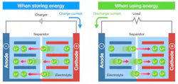
She continued, “One big challenge is limited visibility into the battery cell itself to detect these electrochemical changes before external sensors can react, so the system can proactively take actions to mitigate risk.” The issue is only after a change inside the cell develops and reaches the surface will the battery monitor register a change in cell voltage, pack current, or temperature. By then, the system is reacting to a condition already in progress.
EIS is a fundamentally different approach. EIS analyzes how a battery cell responds to a small AC signal across a wide range of frequencies, usually from a fraction of a Hz to several kHz. By analyzing the cell’s impedance response, EIS provides deeper insight into SOC and SOH, which both influence the impedance. The cell impedance is also sensitive to heat, often reducing impedance by raising ionic conductivity in the electrolyte.
Instead of inferring what’s happening in the cell from “surface-level” signals such as cell voltage, TI said the BQ79826Z-Q1 can measure the impedance that literally impedes the electrochemical processes in the cell, giving it a unique level of visibility.
“I think this is the first manifestation of the technology that can be used in electric vehicles or energy storage,” said Brian Burk, systems engineer and product manager for battery monitor products at TI. “It just really wasn’t possible before [with anything] but lab equipment.”
TI isn’t alone in bringing EIS technology to high-voltage battery packs. NXP recently introduced its first EIS-capable BMS chipset with hardware-based, nanosecond-level synchronization between all devices.
Building EIS into a Battery-Management System
A BMS equipped for EIS uses the same building blocks as a traditional BMS, including several stacked battery monitors (such as the BQ79826Z-Q1) for cell-level voltage sensing and a battery junction box monitor (such as TI’s BQ79881-Q1) for pack-level current sensing, as well as a central MCU that controls the BMS. But it adds several EIS-specific building blocks, including a current excitation source that delivers the AC signal with a sine, square, or other shaped waveform used by EIS (Fig. 2).
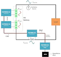
TI said the current excitation can be controlled directly by the battery monitor, or it could be output by other power electronics embedded in the EV or BESS, such as a DC-DC converter, inverter, or pre-charge circuit.
After exciting the cell, the BQ79826Z-Q1 measures the cell voltage response and correlates it with current from the BQ79881-Q1 to calculate cell-level impedance. By comparing impedance magnitude and phase at varying frequencies and monitoring the changes over time, the EIS chipset can measure things that are typically only modeled by the BMS today, such as cell capacity fade and physical stress. Alternatively, the main MCU can also use cell voltages and pack current to calculate the module- or pack-level impedance.
Moreover, the BMS can employ EIS to estimate the core temperature of the cell. This helps accelerate charging rates because it works to keep the battery from overheating or tearing itself apart in the process, said Burk.
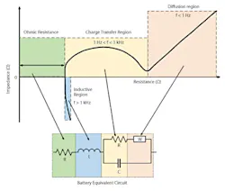
Besides the thermal conditions in the cell, EIS can deliver insights into electrochemical changes occurring in different parts of the cell: the anode, cathode, and everywhere in between. The reactions occur at different speeds. Relatively fast processes such as charge transfer must be captured at high frequencies, while ion diffusion is relatively slow, requiring low-frequency measurements. The regions seen in Figure 3 highlight specific areas in the battery cell that can be monitored using EIS:
- Ohmic resistance (green box, horizontal line): This region shows the DC resistance of the battery electrolyte, and it can be used to pinpoint cell-level defects and other imperfections in the cell potentially caused by manufacturing defects, assembly errors, or damage.
- Charge transfer region (yellow box, semicircle): Charge transfer is a fundamental process that occurs at the interface between the electrode and electrolyte separating the sides of the battery. One of the key physical components in the cell monitored in this region is the SEI layer. The integrity of it is closely related to SOH. If the SEI starts to degrade, the deterioration often indicates the aging of the cell and functions as a reasonable predictor of cell failure.
- Diffusion region (red box, diagonal line): In ion diffusion, lithium ions physically move between anode and cathode to create the current that comes out of the battery. Since impedance can literally impede the movement of the ions, this region helps assess not only SOC and SOH but also the ability of the cell to charge or discharge.
This level of visibility is vital for identifying thermal runaway, a chain reaction where heat builds inside the cell faster than it can be removed, said Burk. One of the primary causes of it is dendrite growth, which can take root long before the voltage, current, or temperature shows that anything has changed. Also called lithium metal plating, this is a buildup of lithium on the anode, which could cause a short circuit inside the cell. By the time the BMS triggers an alert, the condition may be close to irreversible.
While physics-based models are the backbone of a traditional BMS algorithm, combining them with EIS measurements can help detect issues like dendrite growth that develop just under the surface, according to Burk.
The Capabilities of an EIS-Capable Battery Monitor
TI said it upgraded the BQ79826Z-Q1 to handle the very high level of voltage accuracy required by EIS.
Featuring high-resolution analog-to-digital converters (ADCs) and ultra-low noise, the chip can measure voltages within 1.7 mV across its full ambient temperature range of –40 to +125°C and across the cell’s full operating voltage range, enabling more accurate estimates of the SOC. “We reduced the noise caused by the chip itself almost 10 times from the previous generations, so now we can accurately monitor the very, very small signals seen with EIS measurements,” said Burk.
By measuring impedance on top of that, TI said the EIS engine can help estimate SOC and SOH even more accurately, which means making use of more of the battery’s overall capacity. Burk added that “we spent a lot of time improving accuracy from previous generations so that we can measure very small signals in these very large batteries, which is the core IP, and then, we also have the EIS engine that allows it to process this voltage measurement into something useful for the battery designers and the system designers.”
The BQ79826Z-Q1 is intended to be linked to TI’s BQ79881-Q1, which acts as a high-precision monitor for pack current, forming a full BMS chipset. By measuring cell voltage itself and integrating pack current from the BQ79881-Q1, the device can use its integrated EIS engine to measure cell impedance with 1% accuracy (at 1 A of excitation current and 200 µΩ of impedance). “Every single channel of the device can measure the impedance of every single cell, so now you can essentially see inside them,” said Burk.
Accurately sampling the voltage and current of the cells is key to bringing EIS inside the BMS. But it’s not everything. TI said one of the other keys is synchronization of current-voltage acquisitions. The BQ79826Z-Q1 and BQ79881-Q1 both integrate a synchronization protocol that keeps current and voltage measurements tightly aligned, with less than 5 µs of time delay from device to device, reducing the risk of impedance phase errors.
TI noted that it can capture impedance across all of the most important frequency bands for EIS from up to 3.5 kHz and down to 0.01 Hz, using higher frequencies to highlight what happens in the metal conductors and at the surfaces of the electrodes, and lower frequencies for other reactions.
According to TI, the BQ79826Z-Q1 also supports an EIS measurement time that’s 5X faster than existing solutions, sweeping through up to five frequencies at the same time. As a result, it provides a more nuanced understanding of the cell’s internal state.
Is Grid-Scale Battery Storage the Best Fit for EIS?
The ASIL D device has been designed with layers of redundancy to ensure functional safety and rigorously tested to handle the harsh conditions in EVs. But it’s also well-suited for BESS systems, where longevity matters as much as safety and reliability.
"A grid-scale BESS requires a new level of battery monitoring precision,” said TI’s Liu. A BESS — whether connected to the electric grid or a microgrid connected to a data center — can have a very long lifespan, typically lasting 15 to 20 years. EIS can constantly monitor SOH in real time, which is key for operators to identify degradation further ahead of time.
“The prediction of battery life allows [them] to proactively plan their battery replacements before they fail to minimize downtime, which is also huge for a BESS,” said Liu.
A BESS also operates under less dynamic conditions than those in EVs, experiencing predictable charge and discharge cycles with long idle periods between them. This operating profile is well-suited to EIS, which is usually performed while the battery is at rest.
Packed in a 14-mm2 package, the BQ79826Z-Q1 can handle up to 26 cells per device. When paired with the BQ79881-Q1 pack monitor and optional communications bridge, the full EIS chipset can be scaled up to support 250 cells. It also supports passive cell balancing with integrated FETs that supply up to 300 mA of balancing current with programmable pulse-width-modulation (PWM) control. When paired with active cell balancing, data derived from EIS can help redistribute energy across large cell populations in real time, said TI.
According to Liu, the full EIS chipset is “a one-stop shop for different module sizes, different battery cell chemistries, and different mechanical designs. This scalability gives engineers the flexibility to design once and deploy everywhere.”
Besides improving longevity and reliability, TI said that EIS can enhance traditional BMS algorithms reliant on DC cell voltage measurements to estimate the SOC, particularly for LFP cells that are the most popular chemistry for BESS.
These cells have very flat voltage profiles, so measuring the cell voltage alone offers only a limited indication of the remaining charge. EIS complements cell-level voltages by providing a more direct measurement of SOC, reducing worst-case errors from 5% or 10% to less than 2%, according to TI’s Burk. As a result, the BMS can effectively expand the safe operating area (SOA) of the cell, wringing out more charge without undercharging and refueling it without overcharging, both of which can lead to premature aging.
Looking to the future, the BQ79826Z-Q1 has a wider voltage range spanning from 0.0 to 5.5 V, which means that it can support new chemistries being developed for both EV and BESS designs, including sodium ion.
About the Author
 James Morra
James Morra
Senior Editor
James Morra is the senior editor for Electronic Design, covering the semiconductor industry and new technology trends, with a focus on power electronics and power management. He also reports on the business behind electrical engineering, including the electronics supply chain. He joined Electronic Design in 2015 and is based in Chicago, Illinois.