Inductor Current Measurement in Switched Power Supplies

Question: How do you measure inductor current?
Answer: Switched-mode power supplies commonly use inductors to temporarily store energy. In the evaluation of these power supplies, it’s often useful to measure the inductor current to gain a complete picture of the voltage-conversion circuit. But what’s the best way to measure the inductor currents?
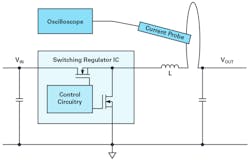
With the buck converter in Figure 1, the voltage at the switching node—that is, the left side of inductor L—switches between the input voltage and the ground voltage at the speed of the switching edges. On the right side of the inductor is the output voltage, which is usually relatively steady. To reduce the interference due to capacitive coupling (electric field coupling), the current measurement loop should be placed on the quiet side of the inductor (Fig. 1, again).
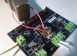
Figure 2 shows the practical setup for this measurement. The inductor is lifted and obliquely soldered back with one of the two terminals on the board. The alternate terminal is connected to the board with the auxiliary wire. This conversion can be accomplished quite easily. Desoldering with hot air is a proven method for detaching the inductor. Many surface-mount-device (SMD) rework stations offer hot air with an adjustable temperature.
Current probes are offered by manufacturers of oscilloscopes. Unfortunately, they’re usually quite expensive. Thus, the question continually arises as to whether the inductor current could also be measured by means of a shunt resistor. This is possible in principle, but there’s a drawback: The switching noise generated in a switched-mode power supply can easily couple into a voltage measurement via a shunt resistor. Consequently, especially at the points of interest, when the inductor current changes direction, the measurement results would not be a true representation of the inductor current’s behavior.
Figure 3 shows the measurement of the inductor current (in blue) for a switched-mode power supply sensed with a current probe compatible with the oscilloscope used. In addition to the measurement shown in blue, a purple marking was added, indicating how the current flow through the inductor would look when the inductor starts to saturate excessively toward the peak currents. This happens when an inductor is selected that doesn’t have enough current rating for a given application. One of the main reasons for measuring inductor current in a switched-mode power supply is the ability to recognize whether the inductor was properly selected or inductor saturation will occur in operation or during a fault condition.
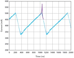
Measurement with a shunt resistor instead of a current clamp would show strongly coupled noise, especially at the peak currents, making it difficult for inductor saturation to be detected.
Sensing of the coil current is very useful in the evaluation of a power supply and can easily be accomplished with suitable equipment.
Frederik Dostal is a Field Applications Engineers at Analog Devices Inc.
About the Author

Frederik Dostal
Power-Management Technical Expert
Frederik Dostal is a power-management expert with more than 20 years of experience in this industry. After his studies of microelectronics at the University of Erlangen, Germany, he joined National Semiconductor in 2001, where he worked as a field applications engineer, gaining a lot of experience in implementing power-management solutions in customer projects. During his time at National, he also spent four years in Phoenix, Arizona (USA), working on switch-mode power supplies as an applications engineer.
In 2009, he joined Analog Devices, where since then he held a variety of positions working for the product line and European technical support, and currently brings in his broad design and application knowledge as a power-management expert. Frederik works in the ADI office in Munich, Germany.
Also check out my:
Comment About the Article
To join the conversation, and become an exclusive member of Electronic Design, create an account today!

Leaders relevant to this article: