Delivering 5G Devices to Market Will Bank on OTA Testing
The biggest challenge in testing 5G devices, as opposed to 4G/LTE, is the reliance on active antenna arrays and high RF frequencies. These frequencies are far higher than what we have ever used before in a commercial communication system. Frequency range 1 (FR1), which will transmit most of the traditional cellular communications traffic, has been designated for 450 to 7125 MHz. Frequency range 2 (FR2) will employ millimeter-wave (mmWave) frequencies (24,250 to 52,600 MHz) to deliver short-range, high-data-rate transmission.
Higher frequency bands combined with extended bandwidths in the mmWave range will place much higher demands on the components for 5G communications devices and systems, including the filters, mixers, amplifiers, analog beamforming chipsets, and antennas.
For FR1, which is sub-6-GHz, testing can still be performed using cables. But at FR2, it will be necessary to consider the entire assembly as one entity, including the antenna, phase shifters, amplifiers, attenuators, and more. Testing needs to be performed at a system level, so that connectors and cables don’t interfere with the system characterization.
New Technologies, More Complexity
FR2 products are becoming very complex. They’re comprised of phased-array antennas; each is built of many antenna elements, every one with its own phase shifter and amplifier, working collectively to steer a signal in a desired direction.
In this case, if testing is performed using a connector that bypasses the antenna array, it’s impossible to gauge how the overall system performs: If the system lacks proper beamsteering or gain, or if the components behind it are too noisy and impact the modulation of the signal, it will not be discovered during the testing phase. Therefore, it’s critical to characterize the entire system—the radio and the phased-array antenna together.
In multiple-input, multiple-output (MIMO) technology, multiple antennas are used at both the transmitting and receiving points, creating a circuit that minimizes errors and optimizes speed. Traditionally, testing MIMO signals has focused on testing the transmitter/receiver system and the quality of the channel. Facilitating commercially feasible testing in 5G devices could be a challenge.
However, when designing a massive-MIMO active antenna system, development engineers face new challenges that include phase-shifter tolerances, thermal effects of the power amplifiers (PAs), and frequency drifts between modules that affect the desired beam patterns.
In an active antenna system, the transceiver front-ends are integrated together with the antenna array, which means that traditional RF output ports are no longer accessible. In addition, a fiber interface replaces the traditional RF input ports for digital I/Q data. Consequently, over-the-air (OTA) testing becomes the default use case for massive-MIMO systems and for modeling the spatial properties of the propagation channel. Due to the different sizes of massive-MIMO systems, testing in far-field conditions requires a variety of shielding environments.
It’s still a bit early to consider what a MIMO test solution for 5G will look like. Nonetheless, we anticipate the need to consider multiple angles of arrival of signal, application of the proper fading channels, etc. Currently, it’s difficult to see what this looks like for FR2.

The 3rd Generation Partnership Project (3GPP), which unites seven telecommunications standard development organizations (ARIB, ATIS, CCSA, ETSI, TSDSI, TTA, and TTC), is actively developing the reports and specifications that define 5G technologies. The project covers cellular telecommunications technologies, including radio access, core network, and service capabilities, which provide a complete system description for mobile telecommunications.
The 3GPP technologies from these groups are constantly evolving through generations of commercial cellular/mobile systems. With its LTE, LTE-Advanced, LTE Advanced Pro, and 5G work, 3GPP has become the focal point for the vast majority of mobile systems beyond 3G. A number of Rohde & Schwarz representatives regularly attend 3GPP’s meetings globally, including those of the standards committees, and the company has contributed input and feedback on testing devices and systems to meet the specifications the organization lays out. When the standards are finalized, they will drive the future certification process.
The major focus for all 3GPP Releases is to make the system backward- and forward-compatible where possible, to ensure that the operation of user equipment is uninterrupted. For 5G, many operators are starting with dual connectivity between LTE and 5G NR equipment—using a non-standalone specification detailed in Release 15 that was completed earlier this year. Care has been taken to build forward compatibility into non-standalone NR equipment, to ensure that it will be fit for use on standalone 5G NR systems.
The Evolution of OTA Testing
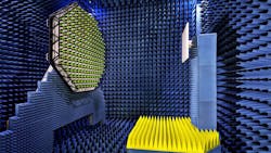
In terms of testing, the standards are changing from connectorized measurements to an indirect far-field measurement using a compact antenna test range (CATR), as it provides the most flexibility and a practical solution moving forward. For example, if you were to measure an FR2 phased array in a true far-field chamber, you would be looking at a range length of several meters, which is impractical.
Today’s systems can execute the antenna characterization or antenna check using test solutions such as a compact antenna range that emulates far-field conditions within a smaller area/footprint. Moving forward, CATR will be the test system of choice to test phased arrays at high frequencies for user equipment.
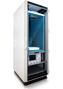
One such compact solution is the ATS800R from Rohde & Schwarz, a vertical rack-mount CATR system (see figure). The device can be placed on a table to characterize the phased arrays and facilitate quick measurements—such as EVM, ACLR, EIRP, or beamsteering measurement—within a 20-cm quiet zone. Although not automated, an adjacent device under test (DUT) can be quickly, fully characterized, which is beneficial for R&D functions as well as for a production environment.
OTA testing will be critical for ensuring that 5G devices will perform in the real world. The 5G device is placed in a test chamber and tested in simulated conditions to see how it responds. In addition to verifying the performance, such testing will certify that products meet specified standards, from both a modulated perspective and an antenna perspective. For example, a vector signal generator can provide a modulated 5G signal, while a spectrum analyzer can help analyze those signals with special measurement profiles, to verify unimpeded transmission between the signal source and the device.
White box testing was sufficient for sub-6-GHz devices for 2G, 3G, and 4G, as the far-field conditions where not as vast as we’ll see with the FR2 band. The latter frequency range is designed for applications that would not allow for a direct line of sight from the DUT to measurement probe. White box testing enables the measurement antenna to look directly at the center of rotation, and the tester knows the antenna’s precise location. Positioning is very important in white box testing, since it uses the far-field condition directly.
While a direct far-field system may allow for testing of larger devices, it’s not practical at higher frequencies. FR2 will require black box testing, either because the antenna position is unknown or there’s a need to measure an entire system or product. This testing method uses indirect far-field (CATR), which doesn’t require exact positioning because an indirect wave measures the device. The measurement system is pointed at the reflector and filters out the spherical wave component to reflect the planar wave back toward the DUT.
Modern highly integrated chipsets, front-ends, and antenna systems require new techniques for OTA measurements in a multitude of development steps. Integrating the antenna or antenna array into the chipset poses challenges in beamforming verification and chipset or amplifier testing. With the use of state-of-the-art test and measurement equipment in lab environments, shielded boxes, or large anechoic chambers, the challenge of OTA testing largely comes down to understanding key challenges in antenna measurement and chamber setup.
It's important to keep in mind that conformance testing will change considerably for FR2 frequencies, leaning toward OTA testing over conducted tests. Engineers will need to know how to calibrate the systems and understand what they are measuring. This will require a bit of homework on their part, perhaps working closely with antenna manufacturers.
5G Production Testing
In addition, 5G production testing, which is still evolving, should be recognized as much more of a challenge for R&D due to the high volumes involved. Production speed ultimately will be impacted by the types of measurements required as well as the length of time it takes to measure and record the measurement.
However, OTA systems for FR2 can be used without a front door in an R&D environment, which saves time placing and removing devices in the chamber and is further conducive to a production environment when a reflector is mounted above the manufacturing line. Such a setup enables a CATR system to easily measure bore sight, off-peak, null definition, beamsteering accuracy, and more.
Production testing for FR2, though, currently remains in the R&D stage for the most part, as manufacturers focus on developing the right design. When 5G becomes mainstream, test-and-measurement designs will need to quickly evolve and align with standards and specifications.
Closing the Knowledge Gap: The New Digital Divide
Millimeter-wave engineering is considerably different than RF engineering. At mmWave, components act differently. At low frequencies, engineers don’t need to account for the phase properties of a wavelength since wavelengths are large in comparison to the component size. But at mmWave, in which frequencies are high and wavelengths are small, the wave properties of the signals must be considered.
As 5G begins to leverage high-frequency mmWave bands, engineers that used to work at RF frequencies will once again need to sharpen their skill sets and adopt new design and testing techniques. To learn more about the technologies shaping our future wireless world, please visit the 5G Learning Center at www.mobilewirelesstesting.com or the Rohde & Schwarz website at www.rohde-schwarz.com/5G.
Clinton Linville is an Application Engineer at Rohde & Schwarz.
About the Author
Clinton Linville
Application Engineer, Rohde & Schwarz
Comment About the Article
To join the conversation, and become an exclusive member of Electronic Design, create an account today!

Leaders relevant to this article: