Rationalizing Test-System Power Requirements
For years, ATE and burn-in developers have used a plethora of programmable power supply products to provide DUT voltage changes defined by a complex test program set (TPS) or even for the more simplistic margin testing required by most electronics manufacturers• burn-in specs. These programmable supplies came in all shapes and sizes with competition driving improvements year after year.
The earliest changes were from linear to switchers, and once the switchers started operating at high enough frequencies so their size and ripple were manageable, the fight has been for faster response times (dv/dt) through regulation and controller techniques. The latest changes include the use of Ethernet to replace the slower and more expensive GPIB interface.
As the test-world upgrades to virtual instruments, a paradigm shift in the overall power architecture is taking place. It started in semiconductor test a few years ago when logic voltage levels began dropping from 15 VDC down to today's 2-VDC to 4-VDC levels. Designers no longer found it effective to provide power to each DUT via a bus connected to a programmable pizza-box supply.
To support the shortened rise times and the higher transistor counts found in today's chips that require more power, it was necessary to build individual power supplies into each DUT test site. Sense lines were shortened, and the built-in current regulation could prevent damaging overshoot spikes across the previously higher impedance power buses.
The power supplies used were compact, fast-acting, programmable DC-DC converters. The bulk DC power that feeds them is unaffectionately dubbed Big Iron, referring to the higher power magnetics in these fixed-voltage bulk supplies. In most cases, the bus voltage used was 48 V, a reasonable level to design the converters to and widely used in the telecommunications industry.
In today's test world, this approach is beginning to get more attention, not only because of the enhanced performance, but also for its compact, programmable design, lower costs, and flexibility. To reduce the size and complexity of the power system, companies now can combine the Big Iron supply with their power conditioner, providing bulk DC power to a VXI or PXI DC-DC converter rack, which offers a selection of programmable and fixed DC supply modules.
This approach is called a PowerHinge. Simply put, it provides a bus that a designer can hang DC-DC converters on, use the voltage as-is, or even hang programmable switchers on, taking different groups of test loads on and off the bus as required for either cycling or per the TPS.
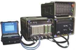
A good example of this is the AN/USM-657A Virtual Instrument Portable Equipment Repair/Tester (VIPER/T). This latest piece of military ATE has been developed for the U.S. Marine Corps to test and diagnose electronic, electromechanical, and electro-optical equipment assemblies and circuit cards (Figure 1).
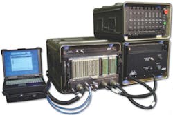
The new system will replace today's Third Echelon Test Systems (TETS) with a smaller and more robust transportable ATE that uses DC voltage available from its high-mobility multipurpose wheeled vehicle (HMMWV) host, driving a rack of DC-DC converters. These DC-DC converters provide fixed outputs for the virtual instrument rack and programmable converters for the TPS requirements.
Another instance of using a PowerHinge is a recently developed actuator tester for a large missile, requiring DC power to be cycled to a group of hydraulic motors driven by high-powered static inverters. The application involves high inrush current rates, something that needs a very low impedance isolation transformer that can handle short-duration increases in current without major size and weight penalties in the magnetics.
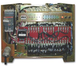
This PowerHinge has several contactors switching power from the same DC bus to various combinations of inverters mandated by the TPS. Control is performed over GPIB. An example of a typical PowerHinge is shown in Figure 2.
In selecting a PowerHinge, a designer must establish priorities. The ultimate configuration will provide clean power, a fresh ground at the point of use, a well-regulated DC bus, an isolated AC bus, and diagnostics to detect external power noise that may affect your equipment.
The PowerHinge begins with a compact and very low impedance isolation transformer. Not all transformers are alike. Windings should be copper, not aluminum, and square, and the design of the assembly should provide the lowest possible impedance. Size will be driven by the power, frequency, and input voltage ranges required of a system, be it transportable or just to accommodate installation in many different countries.
Taps will be provided so your equipment can be operated from any of the standard world voltage levels, whether they are one of the handful of single-phase inputs or the more extensive three-phase inputs. This will save installation costs and assure compensation for regionally low- or high-voltage conditions. In smaller systems, such as transportable units, the various taps can be automatically switched from sensed input line voltages, further expediting the process.
Cleaning up input noise requires removing four major sources of problems. The first is common-mode noise, which fluctuates the phase voltages to ground as well as the neutral to ground. These are removed by the isolation transformer that establishes a fresh neutral/ground relationship on the output, eliminating the problems that can carry over to AC and DC buses.
The next two problems are energy pulses in the form of mono-pulses and ring-pulses. These transients can be formed by disturbances from other equipment on the incoming power lines, noise generated on the mains when capacitor banks are switched in and out for power factor correction or balancing, or lightning strikes near the primary service lines and transformers.
These transients can be lethal to equipment, either instantly or over time. The solution is the addition of a transient voltage suppression system (TVSS) generally made up of metal-oxide varistors (MOVs) that can take the brunt of this unwanted energy, bringing 6,000-V transients down to a more manageable 60 V.
The fourth problem is harmonics, a common issue that manifests itself in test labs and other areas where multiple systems are using the same incoming power lines. These often are the result of nonlinear switched power devices, such as switching power supplies, inverters, or brushless DC motors found in copiers, fans, and printers.
Filtering generally is the best solution, and most good power conditioners provide low-pass filters that kick in at around 1,200 Hz. Harmonics can kill semiconductors over time. They are a major factor in instrument degradation.
In previous Big Iron solutions, a large DC power supply was provided, developing the bus voltage. This switcher may have had a power factor-corrected front end and extensive filtering above and beyond the noise and ripple requirements of the DC-DC converters (Figure 3).
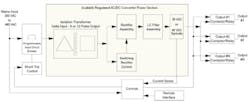
Figure 3. Scalable Regulated AC-to-DC PowerHinge Block Diagram
Please click here to see larger image
Today's PowerHinge, however, provides regulated DC voltage to the hinge bus using 12-pulse SCR phase regulation and a minimum of output filtering. In some cases, only a rectifier is provided, which has little if any inherent regulation but may be adequate for constant input voltages or where tap switching is implemented to reduce the voltage effect (Figure 4).
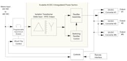
Figure 4. Scalable Unregulated AC-to-DC PowerHinge Block Diagram
Please click here to see larger image
This integration of the DC supply and the power conditioner is a cost-effective and compact means of providing DC and AC power to an ATE or burn-in system. The integrated package cuts down on installation complexity and increases reliability through reduced parts counts.
The PowerHinge can be customized on the output to provide any combination of interconnects, sockets, and plugs. Control of the outputs can be added through Ethernet or GPIB, and you have the flexibility of using any number of available DC-DC converters and their rack assemblies.
PowerHinges are the answer for designers who want to reduce their troubleshooting time due to phantom failures, service departments trying to reduce the number of field support calls and NFF returns, installers who wish to reduce installation times, program managers wishing to increase their application and location flexibility, and users who are space constrained and do not want to deal with the mundane world of power line quality.
About the Author
Robert Close is the military aerospace product manager at Teal Electronics. He has spent more than 30 years in the military and aerospace power and controls market where he has worked in engineering, quality, sales, and marketing. Teal Electronics, 10350 Sorrento Valley Rd., San Diego, CA 92121, 858-558-9000, e-mail: [email protected]
About the Author
Comment About the Article
To join the conversation, and become an exclusive member of Electronic Design, create an account today!

Leaders relevant to this article: