Critical ATE requirements for parametric test of optically networked weapon systems

The use of optically-networked assemblies in defense and aerospace weapon systems is growing rapidly, and the optical test capabilities of the associated ATE is generally inadequate to provide critical fault detection. Optical networking is central to recent platforms such as F-35 and F-22, as well as upgrades to legacy weapon systems such as F/A-18, EC-130H, C-17, and many more to come. The ongoing test requirements for these military applications are unique, requiring new equipment capabilities to augment current test systems, affecting all stages of test in factories, field, and depots. Lacking adequate parametric optical test capability, faults go undetected, assemblies are not interchangeable between weapon systems, and the repair pipeline becomes overloaded.
Optical networking in weapon systems
Fiber-optic networking is displacing electrical cabling in weapon systems, driven by the overwhelming performance advantages such as higher bandwidth, EMI immunity, data security, and support for long cable runs. Additional physical advantages are reduced size, weight, and power (SWaP), as well as lower susceptibility to environmental problems such as corrosion.
These advantages provide support for applications such as
- sensor fusion,
- communications, navigation, and identification (CNI);
- electro-optical targeting systems (EOTS);
- distributed targeting systems (DTS);
- high-definition heads-up displays (HUD); and
- active electronically scanned array (AESA) radar.
Fiber optics is mainly employed to interconnect replaceable electronic assemblies within a weapon system, typically known as Line Replaceable Units (LRU), Weapon Replaceable Assemblies (WRA), or Line Replaceable Modules (LRM). An on-platform problem may be revealed by an operational mission failure or by a built-in-test (BIT) failure. Occasionally, BIT will isolate a problem to the internals of a single replacement assembly, which results in an unambiguous repair action. More often, a fault in one unit will cause one or more other assemblies to fail, creating diagnostic ambiguity. All suspect replaceable assemblies are removed from the weapon system for subsequent analysis in the field, at a depot, or at a supplier facility. Interconnecting cables, which may also be the source of the problem, generally must remain in the weapon system, while suspect assemblies go to a test system. There, the objective is to exonerate good units, identify bad ones, and perhaps to aid in their diagnosis and repair. As the use of optical networking increases with these replaceable assemblies, the limited capabilities of current test systems are creating a significant logistics problem.
Optical networking and new assembly test challenges
Proper operation of fiber-optic networking depends on the successful transmission and reception of light. Optical test processes are not as well established or understood as electrical signal test. Instead of well defined, fixed voltage or current values that differentiate electrical logic levels, optical transmission depends on more complex ranges of optical power level and ratios.
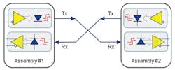
An optical network connection or “link” most often consists of two unidirectional fibers (Figure 1). An assembly uses one fiber for transmission, and the other fiber for reception while communicating with another assembly. Transmitted power is a critical parameter that must fall into a specific range. Excess power from one assembly can saturate the receiver in the partner assembly. Inadequate transmitter power may not allow the receiver to differentiate logic states accurately, resulting in unacceptable network data errors, or total link failure.
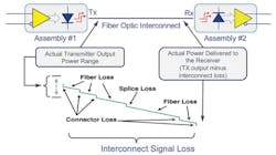
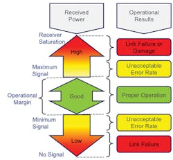
The power at the receive end is the transmit power minus the interconnect attenuation (Figure 2). Receivers must have proper power sensitivity, the ability to discern the logic states over a specific range of light intensity. Receiver sensitivity must be within a specified range; a low-sensitivity receiver needs more transmitted power than one with high sensitivity. The difference between the lowest allowed transmit power and the lowest specified receiver sensitivity is the operational margin, which must be big enough to compensate for the fiber-optic transmission loss, which can vary considerably between installations (Figure 3). In order to ensure interoperability of assemblies in the weapon system, it is imperative that these power parameters are fully tested.
The overall optical network consists of the various replaceable assemblies and the fiber cabling that connects them, any of which may be the source of a failure. Unfortunately, the cables generally remain embedded in the weapon system, where parametric testing is laborious and slow, requiring the weapon system to be taken out of service. Before doing so, it is more economical to replace the assemblies and accurately test them on external ATE.
A key issue is that the attenuation of the UUT fiber path can have significant variation. For instance, each connector in the path introduces variability due to imperfect alignment or surface finish of the mating fibers. This variation must be accommodated by the operational margin provided by the paired transmitter and receiver, which are in two separate assemblies. Transmitter output must be accurately measured to be above the minimum specified level, and receivers must operate properly when the ATE provides the lowest allowed power levels. The transmitters and receivers in each assembly must be within specification to ensure that all combinations of assemblies will interoperate when networked together.
The problem of power variation is further complicated by the environmental effects on transmitter power, receiver sensitivity, and transmission loss over the lifetime of the weapon system. The extremes of temperature, vibration, and contamination may result in parametric variations in performance over time. Again, to ensure interchangeability of assemblies and to provide margin for interconnect variations, the assemblies must undergo accurate optical parametric test. In order to perform these critical tests, the ATE system must have instrumentation designed to deliver optical power management. Today, lacking this capability, most testing takes place at nominal, or crudely controlled power levels, failing to detect problems such as transmitters with improper output power and insensitive receivers. In addition, power tests are often performed with significant manual intervention, reducing test consistency and throughput.
Optical power management requirements
Out-of-specification optical power parameters are the most common mechanism causing catastrophic failure or excess error rate in optical links. The requirements for optical power management directly address this problem, by performing tests on a UUT optical I/O port, which, as previously described, typically consists of separate transmit and receive paths. This port is connected by a two-fiber cable to a port of the ATE instrumentation, which contains a transmit channel and a receive channel. The receive channel must accurately measure the power parameters of the signal sent from the UUT. The transmit channel must accurately vary the power parameters required to test UUT receiver range and sensitivity.
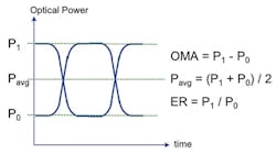
The test parameters (Figure 4) are more complex than those associated with electrical logic levels. The optical power is modulated between two levels to represent the logic states. Key optical values that must be controlled and measured by the test equipment are
- average power (Pavg): the average of the two logic state power levels,
- optical modulation amplitude (OMA): the difference between two power levels, and
- extinction ratio (ER): the ratio of the two power levels.
Commonly available optical components used in the design of many weapon systems operate over a power range of about 10 dB. The test equipment must be able to operate over this entire range, with accurate power measurement and control. Some weapon-system networks are designed for an even larger operational margin, requiring test equipment that can operate over a range as great as 25 dB.
Testing a UUT port entails more than optical tests. Each port employs a serial bus protocol such as Fibre Channel, Ethernet, Serial RapidIO, and numerous others. Each of these protocols may operate at various data rates. The optical power-management test hardware needs to accommodate this range of protocols and speeds. In addition, it needs to team with bus test instruments with the capabilities to interchange and process data exchanged over the UUT port. Thus, optical power management must have the capability to connect instrument ports to UUT ports while the signals pass through the optical test capability.
Most weapon system assemblies have multiple optical ports, and the quantity will increase significantly over time. Multiple buses are often needed for redundancy. Numerous ports may be required to network functions such as smart sensors, transducers, or displays. Assemblies frequently contain a mixture of bus types and speeds to communicate with this array of functions. Some ports may use recently developed bus protocols, while others may be decades old. Basic operation of many assemblies depends on concurrent operation of multiple buses. Throughput-sensitive applications may benefit from parallel testing of multiple UUT assemblies, which requires significant concurrent bus activity.
The parametric tests of optical power management can take place while the bus test instruments are providing very basic protocol-based exchanges with the UUT, accomplished by simply repeating an existing piece of an existing test program for each of the critical optical power tests (Figure 5). Once completed, the network link should be stress-tested under worst-case power conditions, while the bus instrument and the UUT transfer very large quantities of data, performing real-time monitoring for transmission errors. Some assemblies may be provisioned to participate in the standardized bit-error-rate- test (BERT) methodology, designed expressly for this purpose. Other units may require exchanging and testing large quantities of data packets to ensure an acceptable error rate. This combination of parametric optical tests provided by optical power management and the data-intensive error-rate tests of the bus instruments can be thought of as Link Integrity Test.
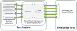
In summary, the requirements for optical power management are that it provide
- multiple optical I/O ports that connect to all of the UUT ports, each of which provides automated parametric test capability;
- multiple optical I/O ports that connect to the ports of multiple bus test instruments, where the quantity of instruments and ports is based on the required bus protocol types, speeds, and demand for concurrent operation;
- a switching path between UUT ports and the bus test instruments, including simultaneous connections that satisfy the demand for concurrent operation; and
- parametric test and switching capability that is independent of bus protocol and speeds employed by the target assemblies.
Weapon system and commercial requirements are different
Two decades ago, when optical networking was first employed in weapon systems, defense and aerospace test systems were able to employ much the same optical instrumentation as commercial applications. Now, defense and aerospace test requirements have evolved, and existing equipment and techniques are inadequate to ensure proper optical network operation.
Defense and aerospace logistics demand decades of support. Weapon systems have diverse interface requirements, mixing various bus types, speeds, and protocols while interconnecting multiple generations of assemblies with an increasing number of optical I/O ports. Long, complex embedded optical cables and connectors interconnect the assemblies that must operate in the harshest of operating environments that age and degrade the optical characteristics. Weapon systems focus on reliability coupled with conservative, carefully planned technology evolution. Weapon system assemblies that fail must be diagnosed and repaired, as they are generally too expensive to discard.
On the other hand, commercial applications for optical networking are mainly in datacenters, where the primary requirement is for ever-increasing bandwidth, focused on one or two bus standards, with operation in a clean, controlled environment. Ethernet is displacing once-dominant Fibre Channel, essentially to the exclusion of all other protocols. While data rates hover at the low end of the 1- to 10-Gb/s range for weapon systems, commercial applications are rapidly moving toward the high end of the 8- to 100-Gb/s range. Failing datacenter equipment is typically discarded, while weapon system assemblies must be repaired. Commercial test equipment experiences rapid obsolescence while defense and aerospace equipment must be supported for decades. As the commercial and military requirements diverge, so does the test equipment that supports them.
Conclusion
Optical networking is on a path to become the primary means for interconnecting assemblies within weapon systems. These platforms have unique optical parametric requirements for test instrumentation used in new test systems, and for augmentation of existing ones. Ensuring error-free operation and facilitating efficient maintenance is of paramount concern. While commercial networks experience frequent upgrades and short product lifetimes, defense and aerospace applications demand the stability of carefully planned, evolutionary change coupled with decades-long logistic support. These differences in use cases have created diverging test-equipment markets. These requirements will drive the deployment of new instrumentation capabilities to support existing and future generations of networked weapon systems properly.
About the author
Tony Erwin is a product manager in the Defense & Aerospace Group for Teradyne Inc. located in North Reading, MA. He has been with Teradyne for 14 years working in various engineering and marketing roles. He graduated from Worcester Polytechnic Institute in 1987 with a BSEE degree and from University of Massachusetts in 1996 with a Master’s degree in Applied Physics.
About the Author

Tony Erwin
Comment About the Article
To join the conversation, and become an exclusive member of Electronic Design, create an account today!

Leaders relevant to this article: