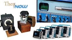
Oscilloscopes Evolve from Humble Displays to Powerful Tools: Now and Then
This article is part of Now and Then series and part of Electronic Design's 70th Anniversary series.
What you'll learn:
- What's an electromechanical oscillograph?
- What model ushered in the era of the real-time digital oscilloscope?
- Examples of the latest powerful equipment.
Waveform analysis of properties such as amplitude, frequency, rise time, time interval, distortion, and other aspects is a significant force-multiplier in the design process. In the beginning, the calculation of these values required manually measuring the waveform against scales built into the screen of the instrument.
Genesis of the Oscilloscope
Early high-speed visualizations of electrical voltages were made with an electromechanical oscillograph (Fig. 1). These were eventually replaced by oscilloscopes based on cathode-ray-tube (CRT) tech to display results. Once referred to as cathode-ray oscilloscopes, CROs were overtaken by digital storage oscilloscopes (DSOs) with thin LCD panel displays, fast analog-to-digital converters (ADCs), and digital signal processors (DSPs).
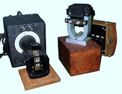
1. An electromagnetic oscillograph measures variations of electric current by having it go through a magnetic coil. (Credit: Rama, CC BY-SA 2.0 FR, via Wikimedia Commons; public domain image scanned by Dale Mahalko, [email protected])
The electromagnetic oscillograph, invented by William Duddell, measured variations of electric current going through a magnetic coil, which induces momentum in the coil that can be directly measured. Some models used a mirror to reflect a beam of light to allow for measurement of minute movements of the coil. Others had a pointer, often fitted with a pen, to record values. A modern oscilloscope may have an integrated display, or it can be an electronic module that plugs into a computer or laptop to process, display, and record waveforms.
The first CRO was created by German physicist Ferdinand Braun, and V. K. Zworykin developed a sealed, high-vacuum CRT with a thermionic emitter in 1931, enabling General Radio to manufacture an oscilloscope that was usable outside a laboratory.
The first dual-beam oscilloscope came in the late 1930s from a British company called A.C.Cossor, which was later acquired by Raytheon. Widely used during WWII for working on radar equipment, the CRT in the uncalibrated device did not produce a true double beam, but rather a split beam made by an additional plate between the vertical deflection plates.
Early oscilloscopes had a synchronized sawtooth waveform generator to provide the time axis. Charging a capacitor with a constant current creates a rising voltage, which is then fed to the horizontal deflection plates to create the sweep. When the capacitor reached a certain point, it would be discharged; the trace would return to the left to start another traverse. The charging current could be adjusted so that the sawtooth generator would have a longer period than a multiple of the vertical axis signal.
The First Real-Time Digital Oscilloscope
Providing a digital solution with analog driveability, the 9400 Dual 175-MHz oscilloscope challenged the industry with a display that shows both the real-time input signal in the upper trace and its computed Fourier spectrum in the lower trace (Fig. 2). Released in 1971, the display used a standard mass-produced television CRT.
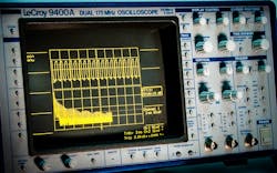
2. The 9400 Dual 175-MHz oscilloscope had a display showing both the real-time input signal in the upper trace and its computed Fourier spectrum in the lower trace.
The 9400 was notable for leveraging LeCroy’s long acquisition memory technology for practical long-memory analysis capabilities at a time when other solutions focused on recreating the viewing experience of an analog oscilloscope.
A few years later, LeCroy came out with the WD 2000 Waveform Digitizer (Fig. 3). With a real-time ADC, memory, and display in one box, the device captured real-time single-shot events. It didn’t have much memory depth—only 20 samples—and it didn’t provide any input signal conditioning (50-Ω, 1-V full-scale only), and it sold for about $20,000. However, it boasted all of the basic features of a digital oscilloscope, and it was fast. Those 20 samples were 1-ns apart in real-time.
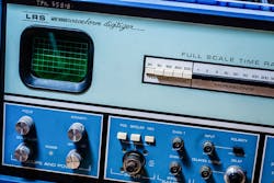
3. The WD 2000 Waveform Digitizer incorporated a real-time ADC, memory, and display in one box.
Sampling (or “equivalent time”) oscilloscopes had been around for a while, offering much higher sampling rates for repetitive signals only, but the WD 2000 was a real-time scope with a small CRT. It achieved its speed through a current-sampling technique derived from the company’s particle physics ADCs, known as “Wilkinson Run-Down” ADCs. They were quite slow, but very accurate, and there were 20 of them compared to more modern designs based on a single “flash” type of ADC.
An interesting note involves Mike Bedesem, the President of LeCroy Research Systems (the company’s name at the time), who was said to have painted the text on the front panels of the WD 2000s by hand. The WD2000 was a harbinger of the company’s 9400 digital oscilloscope, in the sense that it was a convergence of High Energy Physics technology applied to viewing a signal. It, too, like the 9400, introduced in 1984, was a physicist’s oscilloscope.
Pursuing Performance
The electronics industry has always been about developing more and better solutions, and the world of oscilloscopes must stay ahead of the pack. The Infiniium UXR developed by Keysight Technologies was the first series of real-time oscilloscopes to offer high-performance data acquisition with 10 bits of resolution (Fig. 4). The solution offers four simultaneous channels with 5 to 110 GHz of real-time analog bandwidth, each concurrently sampling at 256 Gsamples/s.
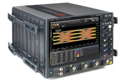
4. The Infiniium UXR from Keysight Technologies offers high-performance data acquisition with 10 bits of resolution.
Providing advanced performance, ultra-low noise, and high signal fidelity, the Infiniium UXR enabled engineers to capture and examine very fast phenomena. The one-, two-, and four-channel models feature a 10-bit ADC and deep memory of up to 2 Gpoints per channel.
Claiming the highest effective number of bits (ENOB) at full bandwidth, the Infiniium UXR has a noise floor of less than 1 mVrms of vertical noise at 110 GHz. The device also ensures accuracy in its measurements with a jitter of less than 25 fs (rms) of intrinsic jitter and less than 10 fs (rms) of inter-channel jitter. Furthermore, the solution enables precise operation with available self-calibration modules.
On top of that, there’s a measurement-acceleration ASIC and memory controller capable of 5 trillion integer operations per second (IOPS). That’s made possible with Keysight’s indium-phosphide ASIC technology for low noise and high signal integrity through full bandwidth time-interleaved sampling. The oscilloscope’s 16 GB of RAM plus a 3.0-GHz quad-core processor and hardware acceleration enable fast processing. And a 15.4-in. capacitive touchscreen brings to light the Infiniium UXR’s ability to measure edges as fast as 2.8 ps.
A Multifaceted Tool
Convergence and integration have been major drivers in the electronics industry, and the test and measurement space is no stranger to that force. The latest oscilloscopes are more than just display mechanisms—they’re full-blown powerful development tools with multiple functions.
For instance, the latest solution from Tektronix, the 2 Series mixed-signal oscilloscope (MSO), is not only powerful, fast, and accurate, it’s also a sleek, lightweight design that includes a high-resolution 10.1-in. touchscreen display (Fig. 5).
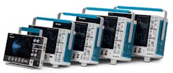
5. The 2 Series mixed-signal oscilloscope has a sleek, lightweight design with a high-resolution 10.1-in. touchscreen display.
Measuring 1.5 in. thick and weighing less than four pounds, the scope can fit into a laptop bag. It’s available in battery-powered configurations, enabling engineers to use the same instrument on the bench or in the field. An entry-level scope with a common tablet-like user interface, the 2 Series MSO is an approachable device for seasoned and novice scope users. With a bandwidth of up to 500 MHz, it claims the widest bandwidth in its category.
An ecosystem of ready-to-use software includes TekScope PC, TekDrive, and VNC. With TekScope PC, visualization and analysis capabilities can expand beyond the oscilloscope to the PC and analysis of waveforms can be performed anywhere and anytime. A collaborative data cloud workspace makes it possible to upload, store, organize, search, download, and share any file type from any connected device, and a built-in VNC server enables the remote connect, control, and viewing of the 2 Series MSO from anywhere, on any device.
The 2 Series MSO features up to four analog channels with a 500 MHz bandwidth, 2.5-Gsample/s rate, 16 channels, 50-MHz AFG, 4-bit digital pattern generator, advanced triggers, protocol decode, DVM, and frequency counter. The capacitive touchscreen and intuitive user interface make it easy to use. An offering of compatible probes and accessories makes the 2 Series MSO capable and versatile to address a variety of applications.
Looking Forward
Oscilloscopes have come a long way, from electromechanical display mechanisms to advanced digital products with a wide bandwidth, fast capture, and high fidelity. From their early iterations that couldn’t even store their data for later analysis, to the latest multi-tool solutions, oscilloscopes have become an even more vital tool for electronic design. The next generation of devices over the horizon promise to be even more powerful, functional, and useful.
Read more articles in Then and Now in our Series Library and in the Electronic Design's 70th Anniversary series.
About the Author

Alix Paultre's Archive
Editor-at-Large
Also check out Alix's main author page for his latest articles.
An Army veteran, Alix Paultre was a signals intelligence soldier on the East/West German border in the early ‘80s, and eventually wound up helping launch and run a publication on consumer electronics for the US military stationed in Europe. Alix first began in this industry in 1998 at Electronic Products magazine, and since then has worked for a variety of publications in the embedded electronic engineering space. Alix currently lives in Wiesbaden, Germany.
Also check out hjis YouTube watch-collecting channel, Talking Timepieces.
Comment About the Article
To join the conversation, and become an exclusive member of Electronic Design, create an account today!

Leaders relevant to this article: