Precision Distance-Measuring Microchip Blends Two Nobel Prize-Winning Techniques
What you’ll learn:
- How two unrelated Nobel prize-winning advances were combined.
- How the phononic-based measurement scheme was devised.
- Details of the arrangement used in the lab-bench test to validate the idea.
It’s not unusual for a technical Nobel Prize to be awarded in recognition for an advancement that’s already had practical applications, usually in well-defined scenarios, such as blue LEDs (2014) or optical fibers for communications (2009). Now, physicists at Delft University of Technology (Netherlands) have gone further, building a new technology on a microchip by combining two Nobel Prize-winning techniques—apparently the first time this has occurred.
Their microchip could measure distances in materials at high precision, including for underwater or medical imaging. Because the technology uses sound vibrations instead of light, it’s useful for high-precision position measurements in opaque materials. These mechanical frequency combs are poised to bring the applications and utility of optical frequency combs into the mechanical domain. (This Nobel-prize “applicability” connection isn’t always apparent, of course; see the sidebar at the end.)
The Delft team used two unrelated Nobel Prize-winning techniques. The first is optical trapping, which uses laser beams to trap even the smallest particles in one spot and then manipulate them with extreme, tweezer-like precision (2018). The second is a coherent optical frequency comb, where a laser is controlled to function as a broad-spectrum light source delivering equally spaced frequencies, while its time waveform appears as a sequence of ultra-short pulses (2005). Both “developments” have become invaluable tools across many unrelated research disciplines.
Microchip Construction
Their microchip consists of a thin ceramic sheet that’s shaped like a trampoline, patterned with holes to enhance its interaction with laser; they monolithically integrated the suspended dielectric membrane with a counter-propagating optical trap (Fig. 1). The laser’s impingement on this membrane created a frequency comb consisting of mechanical overtones (integer multiples) of a single frequency.
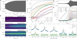
1. (a) Measured displacement of membrane, showing clear growth before reaching a plateau around t = 24 sec. (b) Measured spectrum of membrane motion close to fundamental mode and two of its overtones (5th and 15th). A thermal shift of 9 Hz of the fundamental mode is visible as a 5×9 and 15×9 Hz shift in the overtones (white dashed lines are horizontal to guide the eye). (c) First six overtones increase in power as the membrane displacement increases (markers) in (a). (d) Membrane displacement of a different device (different chip) than (a), showing growth from close to the thermal regime to steady state. (e) Overtone amplitudes extracted from the spectrum of measurement of (d), showing all 35 overtones within the detection bandwidth (black, dotted lines are overtones with numbers between the labeled ones). (f) Spectrum showing measured fundamental mode and some selected overtones in the comb regime (blue) and thermal (green), along with Lorentzian fit with center frequencies nω0 (n integer) and identical linewidths γ0.
When measuring the reflected laser light from the vibrating surface, the team noticed a pattern of vibrations in the shape of a comb that they hadn’t seen before. They realized that the trampoline’s comb-like signature functioned as a ruler for precision measurements of distance.
The setup applied in this work used a commercial laser Doppler interferometer (Fig. 2). Light from the vibrometer (LDV) goes through a microscope objective, which focuses it on the chip containing the membrane resonators. This chip is placed in a vacuum chamber and pumped down until the pressure is <5 × 10⁻⁶ mbar, to reduce gas damping. The reflected light from the membranes is Doppler-shifted due to their out-of-plane motion, which is then detected by the LDV.
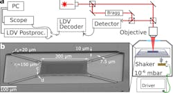
2. (a) Schematic of the laser Doppler vibrometer (LDV) setup, where we access the chip containing the membranes using a microscope objective directly outside a vacuum chamber. (b) Scanning electron microscope (SEM) image of the suspended membrane, with nominal design parameters in white.
The researchers claim that this mechanism unlocks the potential of mechanical frequency combs for sensing, timing, and metrology applications at the microscale, and provides integration with phononic circuits (elastic waves that propagate in solids). This combination of effects results in an easy-to-use mechanical frequency-comb platform that requires no precise alignment nor additional feedback or control electronics, and it only uses a single, milliwatt-range continuous-wave laser beam.
Noted team leader Prof. Richard Norte, “The interesting thing is that both of these concepts are typically related to light, but these fields do not have any real overlap. We have uniquely combined them to create an easy-to-use microchip technology based on sound waves.”
The work is detailed in a seven-page paper with the surprisingly short and direct title, “Mechanical overtone frequency combs” published in Nature Communications, and bolstered by a 20-page “Supplementary Information” posting.
References
Optical Frequency Combs
“20 years of developments in optical frequency comb technology and applications,” Nature Communications.
“Coherent optical frequency combs: From principles to applications,” Journal of Electronic Science and Technology.
Optical Trapping
“Optical trapping,” NIH, National Library of Medicine.
“Optical Trapping,” Teledyne Photometrics.
Damadian and MRI
Raymond Damadian, ““Field-focusing n.m.r. (FONAR) and the formation of chemical images in man.”
“Apparatus and Method for Detecting Cancer in Tissue,” U.S. Patent 3,789,832 (Damadian).
Nobel Prizes and Eventual Applicability
You often can’t tell which Nobel prizes in the “hard sciences” will eventually lead to some practical result. For example, Isaac Isidor Rabi was awarded the Prize in 1944 for his “resonance method for recording the magnetic properties of atomic nuclei” (magnetically induced nuclear precession) and how the nuclei emitted electromagnetic radiation with uniquely characteristic frequencies when the field was removed. This provided interesting insight into quantum mechanics, but otherwise it was considered a “that’s nice, but so what?” discovery—until the 1970s, 35 years later.
That’s when Dr. Raymond Damadian, a physician and experimenter, realized that because tumors contain more water and thus more hydrogen atoms than healthy tissue, there might be a way to use an atomic-level response to see the difference and create images. He then proved this contention via a small-scale medical experiment. Subsequently, he built the first magnetic resonance imaging system (MRI, but at the time called nuclear magnetic resonance or NMR) and produced crude but viable images.
About the Author

Bill Schweber
Contributing Editor
Bill Schweber is an electronics engineer who has written three textbooks on electronic communications systems, as well as hundreds of technical articles, opinion columns, and product features. In past roles, he worked as a technical website manager for multiple topic-specific sites for EE Times, as well as both the Executive Editor and Analog Editor at EDN.
At Analog Devices Inc., Bill was in marketing communications (public relations). As a result, he has been on both sides of the technical PR function, presenting company products, stories, and messages to the media and also as the recipient of these.
Prior to the MarCom role at Analog, Bill was associate editor of their respected technical journal and worked in their product marketing and applications engineering groups. Before those roles, he was at Instron Corp., doing hands-on analog- and power-circuit design and systems integration for materials-testing machine controls.
Bill has an MSEE (Univ. of Mass) and BSEE (Columbia Univ.), is a Registered Professional Engineer, and holds an Advanced Class amateur radio license. He has also planned, written, and presented online courses on a variety of engineering topics, including MOSFET basics, ADC selection, and driving LEDs.
Comment About the Article
To join the conversation, and become an exclusive member of Electronic Design, create an account today!

Leaders relevant to this article: