What's All This Femtoampere Stuff, Anyhow?
A while back, I mentioned1 that we needed a clean test fixture to measure an operational amplifier's input current in the low femtoampere region. But aside from a neat little integrating capacitor made of copper and air, what else did we need?
Here's a list:
A circuit to let us make a high-resolution measurement.
- Ultra-low-leakage sockets.
- A relay to reset the integrator.
- A box to hold and cover up the whole thing.
- A little computer to interpret the data.
- And a scheme for calibration.
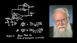
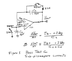
If we take one op amp and force it to integrate the current at its negative input, it can do that job quite well (Fig. 1). But what if its socket is leaky? How can you tell if the error is the leakage of the amplifier or the leakage of the socket?? You'd like to be able to autozero that socket's leakage error out of the circuit. But you can't do that if the amplifier is unable to measure anything when it's not plugged in. A further weakness is that when you try to measure the current at the amplifier's + input, the equation for dVout/dt says that the amount of stray capacitance at the + input affects the scale factor. So, the circuit of Figure 1 would not be very practical.
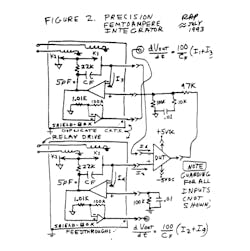
Let's move on to Figure 2. Here, we use two low-leakage amplifiers to test both inputs of one op amp - the Device Under Test, or DUT. When the DUT is removed, the socket leakage and fixture leakage can be calibrated out, in an autozero cycle, so long as they are small and stable.
However, this scheme is excellent primarily because we can pretend to plug in a DUT without actually plugging in anything, and then say, "What is the bias current of this amplifier?" The answer had better be ZERO, give or take a few dozen attoamperes (an attoampere is 10-18 amperes, about 6 electrons per second). Now, in this circuit, the voltage at the + input and at the - input are both constant voltages, so the capacitance from these nodes to ground don't affect the accuracy of the measurement.
Of course, we have to get some good test amplifiers with low noise. The LPC661 and LMC662 are quite adequate, with only small femtoamperes of input bias current that doesn't drift much, and not much noise.
We also need some insulation. If we can't use a lot of Teflon (as I mentioned in my Teflon column) what can we use? Well, we can use some air. It does not leak much, if you only have a little of it. Now, if you have a lot of air, it may permit "leakage" of some electrons, occasionally, due to cosmic rays. But if we keep the total amount of air around the delicate nodes down to a couple cubic inches, that's not so bad.
The other material we like to use for an insulator is the body of the plastic-DIP ICs. This has an impedance up near 1016 ohms, which is about as good as you need. If the part gets dirty, or dusty, or gets fingerprints on it, just wash it in your dishwasher and you can get the package back pretty close to when it first came out of the molding procedure. When you buy an LMxxx in a plastic DIP package, untouched by human hands, it's really a very clean package. Ceramic DIP packages, on the other hand, aren't nearly as low in leakage, more like 1014 ohms - not very good for precision work at sub-picoampere levels.
How about a socket? Can you buy a good Teflon2 socket? If you could, that might simplify things. However, for many IC packages, you can't buy one, so you'll just have to make one, which is MUCH better than anything you can buy.
If you make a pc board in the pattern shown in Figure 3, and then solder some little component jacks3 onto the printed-circuit lands, you can get a socket with less than a femtoampere of leakage, due to the guarding. The guard ring is at the same voltage as the inputs, give or take a couple of millivolts, so there's no direct leakage path from the power-supply buses to the inputs. (Additional notes on guarding are found in various NSC data sheets, such as LF198 or LMC662, available on request.)
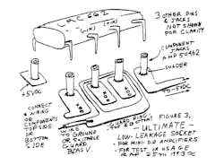
As long as those subfemtoampere leakages are fairly constant from one minute to the next, accuracy won't be hurt at all. This pc board can be made of Teflon material or polyimide if the highest precision is needed. Even glass epoxy board material usually works very well, due to the guarding on both sides of the foil.
How do you make a low-leakage capacitor? In the earlier column, I said that we had made a big 5-pF air-dielectric capacitor with copper-clad walls. For the improved version, we made a small box with copper-clad walls, still about 5 pF, and there's NO detectable leakage from one plate to the other.
When we made a little Teflon capacitor out of several inches of Teflon-insulated twisted-pair wire, well, that also was up near 1017 ohms. Not bad. We evaluated both of these and they both worked well. But my sneaky technician is always trying to find something a little better than my best idea. He tried a 4-inch segment of Teflon-insulated coax cable. In terms of dielectric absorption, it was not quite as good as the air capacitor. But in terms of spurious jumps, it was better, as there was a minimum amount of air around the summing point with fairly optimum shielding. So, once again my technician outsmarted me! I love it!
Okay, wise guy, where do you buy your relay? Or do you make that, too? Well, we were prepared to make or modify an unshielded relay, but we were able to buy a standard Coto relay, model 1240-12-2104.4
This model has a shield between the coil and the reed, which seems to cut down the capacitance to about 0.1 pF.
Then turning the relay off does not really couple very much charge at all into the summing point, electrostatically.
Additionally we shield and guard everything so that there's a wall between the input and the rest of the relay (K1).
Then we add another relay K2 to ensure that the other end of the relay is held at 0 volts during the test, even if the integrator's output goes off to 2 or 3 volts.
So, the 1014 ohms from one end of the reed to the other has no effect, since there's never any voltage across the relay during the test. Also, we drive the relay's coil with the minimum amount needed for pull-in and drop-out - not 12 volts and 0 volts, but 5.5 volts and 2 volts. This helps decrease the jumps.
What do we do to compute the result? We have a Teradyne tester programmed to read the integrator's delta Vout over six 10-second periods. If any 4 give about the same data, it's programmed to admit that the data are valid. We're prepared to ignore cases when a JUMP occurs. But if it's too jumpy, we just reject that part. Right now, after a preliminary study of a few thousand parts, we have yet to find a really bad part at the 20-femtoampere level. That's encouraging, both from the standpoint of the fixture and the amplifier.
How do we put this all in a box? We use a lot of copper-clad to help us build up boxes of every necessary size to shield out all electrostatic interference. We keep power transformers FAR away to cut down on magnetically-coupled noises. We set up four channels of femtoampere testing to look at all four inputs of a dual op-amp. We made things modular, so we can easily pull out a test channel or a socket for cleaning - or for replacement. As with any precision tester, we're reasonably meticulous in our assembly.
We guard the power-supply leads away from the signals and the inputs, because any mechanical motion of the power-supply bus can couple into the summing points. After all, as Q = C × V, we say that by definition I = dQ/dt. Now normally, the major component of dQ/dt is C dV/dt, but there is also a term V dC/dt. If there is a big voltage-such as 5 volts - then V dC/dt can be a significant term.
For example, if dC/dt is 0.01 pF per millisecond, due to vibration of wires, then 5 V × 0.01 pF per milli-second can cause a "noise" of 0.05 pA, or 50 fA. That "noise" goes away if you guard the power-supply buses, and/or if you prevent unwanted motion or vibration.
How do we calibrate the fixture? For a full-scale signal, you can add in a current through a capacitor. In other words, you can get a full-scale signal from this setup by applying a 0.1-volts-per-second ramp to a 1.0-pF capacitor, which represents 100 fA or 0.1 pA. We have an old General Radio standard capacitor; type 1403-K, accurate to 0.1%.
To get calibration at the "Zero" level, do not insert a DUT, close up the box, and do the test. The number of femtoamperes during this "dummy test" should be consistently the same as during an "autozero" test, so the delta should be very small, down in the noise, and consistently below 1 fA. That's important.
We think we can get good results in production with this fixture, although it's pretty early. We can't say that every problem has been vanquished, but we're sure we can solve every problem.
Robert A. Pease / Engineer
- "What's All This Teflon Stuff, Anyhow?," Electronic Design, Feb. 14, 1991.
- Teflon is a trademark of E.I. DuPont de Nemours.
- Type 50462; AMP, P.O. Box 3608, Harrisburg, PA 17105.
- Coto Corp., 55 Dupont Dr., Providence, RI 02907.
P.S. If you're interested in an op amp with IB guaranteed less than 0.025 pA, ask about the LMC6001. - RAP
Originally published in Electronic Design, September 2, 1993. Update April, 3, 2023
RAP Update: One reader wrote in to recommend that for best results, you should add a lot of extra plated-through holes, stitched all around the perimeter of the guard ring. This will help prevent leakage through the VOLUME of the board material. And another reader recommended milling slots instead of the guard ring. That's a pretty good idea, too!
About the Author

Bob Pease
Bob obtained a BSEE from MIT in 1961 and was a staff scientist at National Semiconductor Corp., Santa Clara, CA, for many years. He was a well known and long time contributing editor to Electronic Design.
We also have a number of PDF eBooks by Bob that members can download from the Electronic Design Members Library.
Comment About the Article
To join the conversation, and become an exclusive member of Electronic Design, create an account today!

Leaders relevant to this article: