11 Myths About Oscilloscope Probes
This file type includes high-resolution graphics and schematics when applicable.
Just about everyone who has ever operated an oscilloscope has used an oscilloscope probe at one time or another. Some have had good experiences, while other had unfavorable ones— possibly as a result of their own actions. This article will try to eliminate some myths and half-truths about oscilloscope probes so that their users may obtain more favorable results.
1. For a 100-MHz “signal,” use a 100-MHz probe.
An oscilloscope probe’s bandwidth is specified the same way as the oscilloscopes they are used with—the –3-dB point of product’s response. To illustrate this, if a 100-MHz bandwidth probe were used to measure a 100-MHz, 1-V p-p sine wave, the output of the probe would indicate a 0.7-V p-p amplitude for the sine wave. Therefore, a 100-MHz probe would not be adequate for measuring a 100-MHz signal.
A widely accepted rule of thumb is to use a probe with 3X to 5X the clock frequency or the fastest toggle rate in a digital system. This makes it possible to capture the third or fifth harmonic of the fundamental frequency of the clock or digital signal, resulting in a signal on the screen of the oscilloscope that more accurately represents the true signal with square-like edges. Another useful rule of thumb is that BW × Tr = 0.35 (for 10-90 Tr). Using this rule of thumb, one can either determine the needed bandwidth to measure a given rise time or the fastest edge that can be measured for a probe of a certain bandwidth.
2. Active probes are only required for high-bandwidth measurements.
One of the most often overlooked benefits of active probes is their low loading. Every time a probe contacts a target, that probe becomes a part of the circuit it’s measuring. The effect of this intimate contact between the probe and circuit is referred to as probe loading. The greater the loading, the more the presence of the probe disturbs the signal being measured.
Probe manufacturers specify the input resistance and capacitance of their probes. A typical 500-MHz passive probe is 10 Mohm in parallel with 9.5 pF, while a typical 1-GHz active probe is 1 Mohm in parallel with 1 pF. At dc, the passive probe will look like a 10-Mohm impedance to ground to the circuit being probed, while the active probe will be 1 Mohm. Both are very large impedances, which means there will be no perceivable effect on low-frequency signals. At higher frequencies, the capacitance of the probe will begin to adversely affect the circuit being measured.
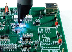
This 1-GHz single-ended active probe (KeysightN2795A) includes an LED "headlight" that can be turned on/off to illuminate small, tight probing locations.
For example, at 75 MHz, the passive probe’s capacitance will present a 150-ohm impedance to ground, while the active probe’s capacitance will present a 2.5-kohm impedance to ground. The smaller capacitance of the active probe will result in less loading of ac signal content above 10 kHz versus the passive probe.
3. All probes are 10:1.
Probes attenuate the signals being measured so that the signal presented to the oscilloscope doesn’t exceed the input range of the oscilloscope. Large attenuation ratios of 10:1, 50:1, 100:1, etc., are used when measuring larger voltages, while small attenuation ratios, such as 2:1 and 1:1, are appropriate for smaller voltages.
Measurement-system noise (oscilloscope noise plus probe noise) increases proportionally to the probe’s attenuation ratio. This becomes an important consideration when choosing a probe. A 10:1 passive probe and a 1:1 passive probe can both be used to measure a 1-V p-p signal, but the 1:1 passive probe will result in much more favorable signal-to-noise ratio.
4. Make a solid connection and it’s good to go.
This misunderstanding probably arises when one sees the vast array of connection accessories included with probes, thinking that simply connecting them to the probe and the target is the only consideration. These accessories are included as a convenience to the user so that they can make simple and quick qualitative measurements—checking to see if a supply is live or if the clock is toggling.
When making quantitative measurements—rise time, period, overshoot, etc.—it’s best to remove the accessories and use the shortest connection possible. The longer accessories add inductance in the signal path of the probe and greatly reduce its bandwidth while simultaneously increasing the probe’s loading of the circuit being tested.
5. Ground is ground.
This statement seems self-evident, but this may not be true for an oscilloscope probe. The error occurs in how the probe is connected to ground. The ground lead of a probe has the properties of an inductor—its impedance increases proportionally to frequency. The longer the ground lead, the more inductive it is and the lower the frequency at which its impedance becomes problematic.
What happens is that return current flowing down the shield of the probe encounters this impedance. This will reduce the bandwidth of the probe and create ringing on the signal being observed. In addition, the longer the ground lead, the larger the loop area created by the lead and the bigger an antenna it becomes for picking up stray noise. It’s always best to use the shortest ground connection possible.
6. Use a current probe and a voltage probe to measure power.
Power = voltage × current, so the above statement appears to be true. The falsehood is that the statement isn’t complete. To accurately measure power with an oscilloscope, the voltage probe and current probe need to be de-skewed.
The electrical lengths of the voltage probe and the current probe usually aren’t the same. This is due to cable lengths and device delays, and results in signals arriving at the oscilloscope at different times for the two probes. The effect is that for a system like a switching-mode power supply, in which both voltage and current are dynamically changing, the product of voltage × current will be incorrect.
De-skewing the probes will remove the difference in signal transit time between the two probes and correct the error. The documentation for the probes being used will contain detailed information about this procedure. It usually entails probing a known signal, such as a de-skew fixture provided by the manufacturer, with probes and aligning them in time by adjusting the channel delay on the oscilloscope. Many oscilloscopes have a built in de-skew operation that automates the time alignment once the calibrating signal is probed.
7. Use dc block/ac coupling to remove dc.
Many times the signal of interest to be analyzed is an ac signal riding on top of a relatively large dc signal. A popular example of this is measuring ripple and noise on dc supplies. The “old school’” approach is to put a large capacitor in series with the probe to reject the dc component so that the signal could be centered on screen and zoomed-in on for analysis. An even better way to do this is to use a probe with the “probe offset” capability, such as Keysight’s N7020A Power Rail probe.
Probe offset is when the scope and probe inject a nulling voltage into the probe, ideally behind the large resistance tip resistor of the probe. The benefit of using probe offset is that it only removes the dc. When using a dc block, low-frequency content is also filtered out. In the case of measuring ripple and noise on a dc supply, the dc block could filter out low-frequency supply drift and supply compression.
Another advantage of probe offset is that the user dials in the offset. As a result, the oscilloscope knows how much dc is removed, and can display the information and use it in any math or automated measurements.
8. Don’t put scope probes in a temperature chamber.
There was a time when this was a true statement. Today, though, several high temperature options are available to users. For example, Keysight offers a range of voltage and current probes that can be used in environmental chambers and operated over temperatures ranging from –50° to +150°C. In addition to their high temperature capabilities, these probes also offer longer cables so that they can reach from inside the chamber to outside the chamber where the test equipment resides.
9. Current probes aren’t useful for measuring “small” current.
Many users of oscilloscope current probes have had the unpleasant experience of trying to measure small current (1-50 mA) and found that the current probe’s variation from measurement to measurement is greater than the current being measured. This is due to a variety of factors, such as variations in the position of the wire running through the probe, thermal drift of the probe, residual magnetization, or external signals coupling into the loop of wire used to measure the current.
A new breed of current probes, such as Keysight’s N2820A High Sensitivity Current probe, are custom-tailored to measure very small current (microamps and below). They jettison the previous approach of sensing magnetic fields and instead rely on Ohm’s law. These differential-voltage probes measure the voltage across a sense resistor ranging from 1 mohm to 1 Mohm and display the resulting measurement in amps on the oscilloscope. This approach eliminates the previously mentioned sources of error, allowing users to accurately measure very small current with an oscilloscope.
10. Using two probes while driving the scope is impossible.
Two products from probe manufacturers that receive little publicity and often go unnoticed are the probe holder and probe positioner. These handy accessories work as an additional hand, enabling the user to operate the oscilloscope while probing many locations simultaneously. They range in complexity from a simple bipod that attaches to the probe creating a stable tripod (with the probe being the third leg) to multi-axis—infinitely positionable holders that can hold the probe in orientations that allow for probing vertical as well as horizontal targets.
11. It’s hard to probe modern high-density targets.
Probing of high-density targets isn’t as difficult as many users might think. Probe manufacturers are always creating new accessories or lines of probes to facilitate probing of high-density targets. They have shrunk the diameter of new passive probes to make it easier to see the target, or in some cases, added headlights to their active probes to illuminate the target. There’s even a novel magnetic probe head, the Keysight N2851A, with which users solder attach a small probe connection point to their target; the probe connects to the probe site and is held in place by the small magnets within the probe. The probe can then be easily moved from location to location, letting the magnets do the work.
This file type includes high-resolution graphics and schematics when applicable.
About the Author

Kenny Johnson
Probe and Interconnect Expert
Kenny Johnson is a technical lead responsible for project definition, market investigation, and product development of Keysight’s oscilloscope probes and accessories. He has designed logic-analyzer probes; managed logic-analyzer hardware, ASIC, and software development; and was a marketing product line manager for logic analyzers before joining the oscilloscope probe team.
Kenny has been an HP/Agilent/Keysight employee for 30 years. Before that, he attended Kansas State University, where he earned a B.S. in mechanical engineering. He holds 20 patents related to electro-mechanical designs. Kenny enjoys running, biking, skiing, and canyoneering.
Comment About the Article
To join the conversation, and become an exclusive member of Electronic Design, create an account today!

Leaders relevant to this article: