This file type includes high-resolution graphics and schematics when applicable.
G.fast is a new copper broadband technology that enables throughput of better than 1 Gb/s over a single twisted pair. The technology is based on a signal modulation scheme very similar to the DMT modulation used in VDSL2, with one notable exception, G.fast transceivers utilize time-division duplexing instead of the frequency-division duplexing used in VDSL2.
G.fast also borrows many other advances from VDSL2, including seamless rate adaption (SRA), bit swapping, retransmission, dying gasp, and vectoring. In addition, G.fast includes some new improvements such as the robust management channel (RMC), dynamic resource allocation (DRA), and fast rate adaption (FRA). Each of these features possesses a unique challenge in testing the transceiver’s functionality.
The key to successful deployment of any broadband technology is robust testing to ensure the core features of the deployed transceivers comply with the specifications; that it interoperate with systems from other manufacturers; and it doesn’t negatively impact the operation of other systems deployed in the broadband network. These testing requirements are no secret, as they have been followed for the many years of successful broadband deployments.
Making a Test Plan
Operators typically perform detailed lab tests, followed by trial deployments, and an eventual mass rollout. For the case of G.fast, the members of the Broadband Forum chose to pool many of the testing resources in the development of a detailed test plan, covering the functionality of G.fast systems and some basic performance and stability metrics. In this article, we’ll explore how some of these items are tested and/or how they affect the testing of other features.
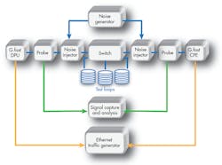
Before diving into the depths of the G.fast test cases, we’ll start with a brief explanation of the most common G.fast test setup. It covers the requirements for approximately 75% of the test cases in the Broadband Forum certification test plan, including the test cases for all of the features listed above. The key pieces of test and measurement equipment in the setup are the test loop and its associated switch, noise generator, digital signal analyzer (signal-capture system), and Ethernet traffic generator (Fig. 1).
Bit Swapping
Let’s start our exploration of G.fast testing by looking into the bit-swapping feature and its associated test case. Bit swapping allows a receiver to change the allocation of bits between subcarriers, due to a loss (lowering) of the signal to noise margin for the impacted carrier. In this event, the receiver requests the transmitter to alter the bit loading, moving the bits to other tones where there may be additional capacity.
To test the bit-swapping feature, the ID-337 test plan injects noise at each side of the test loop, where the noise level is elevated for a specific set of subcarriers. The G.fast systems are allowed to initialize the G.fast line in the presence of this noise. Once the line is stable, the noise level is lowered for the original set of subcarriers, while being increased for a different set of subcarriers. The end result is the transceivers must alter the bit loading over the sub carriers, without changing the total data rate for the connection.
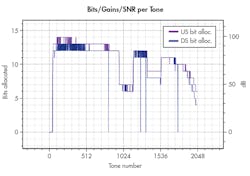
Figure 2 shows the bit loading at the start of the test, where you can clearly see the impact of the higher noise levels over subcarriers 975 to 1150. For the test to work correctly, the seamless-rate-adaption (SRA) functions in the transceivers must be disabled.
Seamless Rate Adaption
SRA allows the receiver to request a change to the total bit allocation, changing the data rate in response to changing noise conditions at the receiver. The rate changes are triggered by a change in the average signal-to-noise-ratio margin (SNRM). Generally speaking, an increase in noise on the G.fast line is met with a decrease in the operational bit rate of the line, with the inverse true for a decrease in noise on the line.
For this test, it’s important to ensure the noise injected on the line impacts all tones used by the receiver, so a bit-swapping operation would not be able to “reallocate” bits to any available tones. Another important consideration is the timing of the noise changes injected on the line and when the status is read from the devices. With the G.fast specification, the timeout for SRA operations can be configured, and that timeout has to happen before the SRA operation(s) actually occurs on the line.
Once the SRA operation(s) has completed, the SNRM should be within the configured SRA bounds. However, another process running independent to the SRA operations keeps the current SNRM information synchronized to the far end of the loop. That is, the near-end receiver needs to communicate its current SNRM to the far-end transmitter, and the chip sets select that update interval during the G.fast initialization process. The tests must then wait for the full timeout of both the SRA configuration and the maximum SNRM update interval to ensure the recorded SNRM information is accurate.
Retransmission
Another key concern of service providers is system stability and robustness against noise on the G.fast line. The G.fast specifications include support for physical-layer retransmission of data that was corrupted by noise on the copper pair. Retransmission works by storing data transmitted over the line for a small (only a few symbols worth) amount of time, allowing the data to be resent if it was lost during transmission. This retransmission typically occurs in less than a few milliseconds, preventing the need for higher layer retransmissions (TCP) that take far longer.
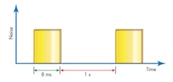
To test the retransmission functions, impulse noise is injected onto the G.fast line, with specific time-domain patterns. The patterns, typically a repeating set of noise pulses, are designed to impact a specific number of the G.fast symbols. Retransmission configuration allows for control over the number of symbols that are stored (and could be retransmitted). By adjusting the pulse width and repetitions, it’s possible to verify these configurations. One set of pulses could be fully recovered by retransmission, while another set of pulses would cause errors where data was no longer available for retransmissions (and was lost from the errors).
Figure 3 shows a typical example of the SHINE (single high impulse noise event) pulse noise pattern used by the G.fast certification testing. In these tests, the Ethernet traffic generator is also used to ensure that the retransmission systems fully recover the lost symbols, resulting in no lost or dropped Ethernet frames.
Testing for Performance
Lastly, performance testing is also included in the plan. The performance test cases, both single-line and multi-line, verify that the set of transceivers are able to achieve sufficient bit-rate performance over a variety of loop lengths.
The multi-line case requires that the DPU and CPE support the vectoring functionality, which makes it possible to cancel the far-end crosstalk that occurs between the wire pairs. Also, the multi-line test case uses a typology known as non-co-located setup, where each CPE is a different distance from the DPU. However, in all cases, the pairs travel in the same binder (grouping) as other pairs, which causes the crosstalk to occur.
More information about the cable used in the test setup can be found in this white paper. The performance requirements include both the physical-layer bit rate and the supported data rate for Ethernet frames traversing each link.
In conclusion, the G.fast technology includes a number of features to ensure that it will perform well in a variety of deployment cases from operators around the world. The forthcoming G.fast certification program will make certain that devices completely and correctly implement these features and are able to interoperate and achieve a level of performance to meet operator needs.
About the Author
Lincoln Lavoie
Senior Engineer, Broadband Technologies, UNH-IOL
Lincoln Lavoie is a principal engineer at the University of New Hampshire InterOperability Laboratory (UNH-IOL). In this role, he is responsible for the technical management of the broadband access technology grounds, including NFV, Wi-Fi, DSL, Gfast, GPON, and PoE. In addition to his duties with the UNH-IOL, Lincoln participates in many industry organizations, including the Broadband Forum (BBF) and OPNFV. Lincoln currently holds leadership / editor roles within the BBF and contributor / committer roles within OPNFV.
Lincoln received his BS, summa cum laude, in electrical engineering from the University of New Hampshire in 2003 and received a Master of Science in the same discipline in 2008.


