Performing In-Circuit Inductor and Transformer Measurements in SMPS (.PDF Download)

In switched-mode power supplies (SMPS), magnetic components, namely inductors and transformers, play critical roles. Much of the SMPS design process relies on component specifications and simulation models. However, due to actual signal conditions, parasitics, temperature, and other environmental factors affecting magnetic components’ performance, a power supply may not perform exactly as predicted by specs and simulations. As a result, in-circuit measurements of inductors and transformers under operating conditions are critical to ensuring reliable real-world performance.
With the right tools on hand, making these measurements doesn’t have to be difficult or time-consuming. We’ll first review the basic theory of inductors and transformers, especially as it relates to in-circuit measurements. We’ll then walk through the use of oscilloscope and probes during power-supply operation, and explore the use of induction measurements and B-H curves to gain performance insight.
Inductor Theory
Faraday’s and Lentz’s laws tell us that the current through an inductor and the voltage across the inductor are related as:

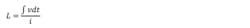
This shows that inductance can be thought of as the extent to which a changing current results in an opposing voltage. By integrating, rearranging, and ignoring the sign, we can get: