Today’s Designs Require a Verification Continuum

Verification has long been a major challenge in the chip development process, and its growing faster than chip complexity itself. The emergence of software-centric systems-on-a-chip (SoCs) in the mobile and Internet of Things markets only accelerates this trend with the added importance of enabling software development and testing prior to silicon.
Early availability of a high-performance platform for software bring-up is becoming a critical new requirement for leading verification teams targeting today’s shrinking SoC market windows. In fact, a recent analyst report found that “the need to develop and fully verify the software can be a key factor in how rapidly new products can be brought to the market.”1
This file type includes high resolution graphics and schematics when applicable.
This is a big change from just a few years ago, when functional verification meant one thing: simulation. Whether the simulator was fed with directed tests or random vectors, you simulated your design until becoming convinced that it was working.
Times have changed dramatically since then. The introduction of technologies such as code coverage, testbench automation, assertions, and debug automation, as well as formal property checking, have dramatically increased productivity. They also find bugs that simulation alone might not uncover. Now these technologies are widely adopted and integrated in mainstream verification flows.
FPGA-based emulation and prototyping, as well as virtual prototyping, are emerging as key new technologies in the verification flow to address ever-increasing software content in today’s SoCs . They provide the performance needed to execute billions of cycles of testing to verify key SoC functions, such as low-level firmware and operating system boot, or to complete pre-silicon performance or power validation. These technologies originated largely as point tools to augment the simulation-dominated verification process. They were typically created by smaller companies that were eventually acquired by larger companies.
As these verification technologies deploy onto more complex SoCs, it’s become obvious that they must work together not as a collection of independent functions, but as a single flow – a continuum that allows a seamless transitioning back and forth between them as needed. However, the reality of technologies with different origins is that inefficiencies will permeate language support, flow setup, execution semantics, and debug. Leading IC developers are searching for solutions to address this discontinuity and help “shift-left” their schedules; i.e., move verification tasks up in the cycle to start software bring-up earlier and complete verification sooner. Let’s take a closer look.
Verification Discontinuities Slow Time-to-Market
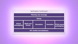
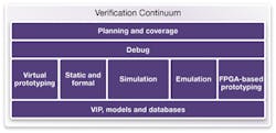
Verification requires many different engines for different parts of the IP and SoC verification flow (Fig. 1). At the earliest stages of the design, developers may employ virtual prototyping for architecture exploration and early software development. As RTL becomes available, a variety of static, formal, and simulation technologies are deployed to find and eliminate design bugs. As the RTL matures, verification teams often migrate their design to a high-performance emulator for long SoC verification tests and early software bring-up. Finally, they may move the design to an FPGA-based prototype for even more performance required for software development and system validation with real-world interfaces.
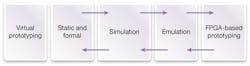
With each of these verification steps, engineers face the challenge of “bringing up” a design on the next engine after running on a previous engine. It can be a very complex, difficult, and time-consuming process. Each of the engines may support or interpret RTL slightly differently, or have some other incompatibility requiring changes to the RTL or supporting collateral. These verification discontinuities—from static/formal to simulation, from simulation to emulation, from emulation to prototyping—can add weeks or months to the verification schedule and introduce risk given the occasional need to do manual design changes.
Debug presents another major challenge during this process. As a design progresses from simulation to emulation to prototyping, each engine in turn provides a higher level of verification performance. However, each step in this progression also provides decreased debug visibili—if a bug is encountered, it’s more difficult to diagnose and fix.
As a result, engineers often must move the design back to an earlier engine—from prototype to emulator or from emulator to simulator –to localize and correct the bug. The initial design bring-up challenge is experienced again in reverse, and many times engineers have to go to extraordinary lengths to reproduce the bug on the other engine. These debug discontinuities can introduce even more delay, often at a critical point near the end of the chip-development schedule.
Leading Companies Look to “Shift-Left”
A new set of requirements is emerging from market-leading chip companies who are looking to “shift-left” their verification timelines by bringing these verification technologies together in a seamless flow:
• Fastest engines: Performance has, and continues to be, the top requirement for verification teams. Each engine in the flow, including virtual prototyping, static and formal verification, simulation, emulation, and FGPA-based prototyping must be best-in-class in terms of performance.
• Unified compile: Simulation remains the cornerstone of verification, and designers want their compile flow to be built around the leading simulation engine, proven on complex chips. Once a design is compiled for simulation, it should be seamless to bring up the design in emulation or FPGA-based prototyping. Language support should be consistent; execution semantics the same; compile scripts common.
• Unified debug: Up to 50% of verification time is spent in debug, and engineers demand to use the most popular and productive debug environment available throughout the flow. As a design moves between engines, the debug environment and database should be consistent, enabling debug to proceed fluidly between engines and abstraction levels, and across both hardware and software.
• Strong support for FPGA-based emulation and prototyping: Leading semiconductor developers have concluded that FPGA-based emulation is the best choice today and in the future, providing enduring performance, refresh-rate, and cost/scalability benefits when compared with emulators based on custom chips. FPGA-based prototyping provides even higher performance and access to real-world interfaces. To take advantage of these benefits, the verification flow must be designed to take full advantage of FPGA-based hardware platforms.
The New Industry Solution
The primary barriers to easy migration between key engines in the verification flow include the compile and debug flows. Unification in these areas can smooth the friction encountered when moving between mutually uncorrelated tools. As an example, Synopsys recently announced its Verification Continuum Platform, and its efforts illustrate how such a new platform can enable earlier software bring-up by reducing friction between the key engines in the verification flow (Fig. 2).
The first step in unifying the compile flow is to adopt a common front end. Given that simulation is generally the most mature verification technology and all designs are simulated at some point, it makes sense to build a unified compile flow around the simulator. Synopsys chose to build its Unified Compile technology around the proven VCS solution, used to verify highly complex designs. With Unified Compile, designs that compile for simulation will easily compile for other tools in the flow.
The simulator front end acts as a unified entryway into the verification flow. Of course, each tool needs something different – formal analysis may need properties; simulation needs a testbench and a compiled design; and emulation also needs a compiled design – but one that’s different than the simulation version. The simulator front-end feeds specialized back-ends that perform engine-specific optimizations (Fig. 3).
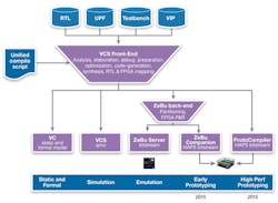
This means that there will be a single, consistent set of inputs for the design, including the RTL, the UPF file for power intent, the compile script, and relevant verification collateral. A design compiling in simulation will easily compile in emulation, and a design compiling in emulation will easily compile in prototyping. This eases transition between engines and minimizes risk of introducing new bugs through engine-specific design or collateral changes.
One might think that the purpose of verification is to find bugs, but, in fact, that’s only half the battle. After identifying a failure, the root cause must be found and – critically –must be fixed. This is where the right-to-left debug flow in Figure 1 comes into play. Particularly with simulation, emulation, and prototyping, any failure constitutes an event: Given a particular state of the system, a specific stimulus at a specific time has created an unexpected outcome.
Synopsys chose to build its Unified Debug architecture around the popular Verdi debug solution, providing a common debug environment and database regardless of the engine being used. This is important because finding the root cause of the bug may require a different engine from the one that found the bug.
A given bug might have been found while prototyping, for instance, because the faster performance of the prototyping platform may have allowed a more comprehensive test to be executed, uncovering the problem. The prototyping board, however, will have lower debug visibility than the emulator. Therefore, re-running a specific subset of the verification in the emulator may be necessary—or perhaps in the simulator, which provides maximal visibility. The challenge can be multiplied during initial model bring-up, where the engineer isn’t sure if the issue is an artifact of the model or represents the actual design functionality.
This means that each of these tools must have the same understanding of the failing event and the expected outcome, and the ability to reproduce the event with the higher-visibility engine. The best way to guarantee this is by providing consistent execution semantics, supporting unified verification environments, and implementing a single debug database shared between all tools. In the Synopsys Verification Continuum, a unified runtime architecture ensures that a verification environment created for one engine (e.g, emulation) can be easily reused on another engine (e.g., simulation) with a standard language-based interface. Congruency between the engines ensures that each engine will generate consistent results.
This file type includes high resolution graphics and schematics when applicable.
Debug efficiency also benefits from the Verification Continuum’s unified compile technology. In the past, different models of the design for the different tools might actually be functionally different if they’ve lost synchronization. In such a situation, it may be impossible to take a bug found, for example, during emulation and recreate it in the simulator. That’s because the simulation model of the design may not contain the bug. By using a single set of design inputs, all tools can see the same design, ensuring that a bug identified in one tool will be available for diagnosis in any of the other tools.
A Major Industry Transition
Such a unified verification flow may feel like a relief to overworked verification engineers, but it will be essential for realizing the next generation of designs. Such designs will require verification of yet more complex logic and software in the same or even less time as allocated for today’s designs. A major industry transition like this doesn’t happen overnight. It requires a solid foundation, and a development path that makes the shift from an industry focus on individual point tools and engines to a seamless high-performance platform. Industry leaders recognize this is critical to ensure that the most complex, software-centric SoCs can be developed and brought to market as quickly as possible.
Reference:
1. “Global System IC Industry Service Report,” July 2014, International Business Strategies Inc.
About the Author
Tom Borgstrom
Director of Marketing
Tom Borgstrom is a director of marketing at Synopsys, where he is responsible for the ZeBu emulation solution. Before assuming his current role, he was director of strategic program management in Synopsys’ Verification Group. Prior to joining Synopsys, he held a variety of senior sales, marketing, and applications roles at TransEDA, Exemplar Logic, and CrossCheck Technology and worked as an ASIC design engineer at Matsushita. He received bachelor’s and master’s degrees in electrical engineering from the Ohio State University.
Comment About the Article
To join the conversation, and become an exclusive member of Electronic Design, create an account today!

Leaders relevant to this article: