What’s The Difference Between A Dipole And A Ground Plane Antenna?
>> Website Resources
.. >> Library: TechXchange
.. .. >> TechXchange: Antenna Design 101
Download this article in PDF format.
Every wireless device needs an antenna. This conductive mechanical device is the transducer that converts the radio frequency (RF) power to be transmitted into the electric and magnetic fields that make up a radio wave. It also converts the received radio wave back into an electrical signal. An almost infinite number of configurations is possible for antennas. However, most are derived from two basic types: dipole and ground plane antennas.
Table Of Contents
• Antenna Fundamentals
• The Dipole Antenna
• The Ground Plane Antenna
• Summary
• References
Antenna Fundamentals
A radio wave comprises an electric field perpendicular to a magnetic field. Both are perpendicular to the direction of propagation (Fig. 1). An antenna creates this electromagnetic field. The signal to be radiated by the antenna is developed in a transmitter and then sent to the antenna by way of a transmission line, usually coax cable.
1. The lines are the magnetic and electric lines of force that travel together and support one another as they move outward from the antenna.
The signal voltage develops an electric field around the antenna elements. The current flow in the antenna produces a magnetic field. The electric and magnetic fields combine and regenerate one another according to Maxwell’s famous equations, and the combined wave is launched from the antenna to travel through space. At the receiving site, the electromagnetic wave induces a voltage in the antenna, which converts the electromagnetic wave back into an electrical signal that can be further processed.
A primary consideration in the orientation of any antenna is polarization, which refers to the orientation of the electric (E) field with the earth. It is also the orientation of the antenna elements with respect to the earth. A vertically mounted antenna, perpendicular to the earth, radiates a vertically polarized wave. So, a horizontally positioned antenna radiates a horizontally polarized wave.
Polarization also can be circular. Special configurations such as helical or spiral-wound antennas can launch the wave into rotation, creating a circularly polarized wave. The antenna may induce either a right-hand or left-hand rotation.
Ideally, the antennas at both the transmitting and receiving sites should have the same polarization. At frequencies below about 30 MHz, the wave is usually reflected, refracted, rotated, or otherwise modified by the atmosphere, earth, or other objects. Therefore, polarization matching at the two sites is not critical. At VHF, UHF, and microwave frequencies, polarization must be the same to ensure maximum signal transfer. And, note that antennas exhibit reciprocity—that is, they work equally well for transmitting or receiving.
The Dipole Antenna
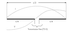
The dipole antenna is a half-wavelength structure made of wire, tubing, printed-circuit board (PCB) copper, or some other conductive material. It is divided into two equal quarter wavelengths and fed with a transmission line (Fig. 2).
The lines show the distribution of electric and magnetic fields. One wavelength (λ) is:
λ = 984/fMHz
where wavelength is in feet and the frequency is in MHz. One half wavelength is:
λ/2 = 492/fMHz
The actual length is usually shortened depending on the size of the antenna conductors. A better approximation to electrical length is:
λ/2 = 492 K/fMHz
K is a factor relating conductor diameter to length. It is 0.95 for wire antennas at a frequency of 30 MHz or less. Or:
λ/2 = 468/fMHz
The length in inches is:
λ/2 = 5904 K/fMHz
The K value is smaller for larger diameter elements. For half-inch diameter tubing, K is 0.945. A tubing dipole for 165 MHz would have a length of:
λ/2 = 5904(0.945)/165 = 33.81 inches
or two 16.9-inch segments.
The length is important because the antenna is a resonant device. For maximum radiation efficiency, it must be tuned to the operating frequency. However, the antenna does operate well enough over a narrow range of frequency just like a resonant filter.
The antenna bandwidth is a function of its structure. It’s usually defined as the range where the antenna standing wave ratio (SWR) is less than 2:1. SWR is determined by the amount of reflected signal from the antenna back down the transmission line feeding the antenna (see “Standing Wave Ratio,” below). It is a function the antenna impedance with relationship to transmission line impedance.
The actual impedance of the antenna at its center feedpoint varies with frequency and antenna height. At resonance and one half wavelength above ground, the antenna impedance is approximately 73 Ω resistive. Off resonance, the antenna impedance will include either an inductive or capacitive reactance component.
The ideal transmission line is a balanced conductor pair with a 75-Ω impedance. Coax cable with a 75-Ω characteristic impedance (Zo) can also be used. Coax cable with a 50-Ω characteristic impedance can also be used since it is a good match to the antenna if it is less than one half wavelength above ground.
Coax is an unbalanced line since RF current will flow on the outside of the coax shield, creating some undesirable induced RF in nearby devices, although the antenna will work well enough. The best feed method is to use a balun at the feedpoint with coax cable. A balun is a transformer-like device that converts balanced signals to unbalanced signals or vice versa.
The dipole may be mounted horizontally or vertically depending on the desired polarization. The feed line ideally should run perpendicular to the radiating elements to avoid distorting the radiation pattern, so the dipole is most often oriented horizontally.
An antenna’s radiation pattern depends on its structure and its mounting. The physical radiation is three dimensional but is usually represented by both horizontal and vertical radiation patterns.
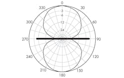
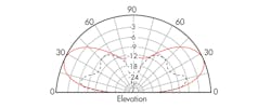
The horizontal radiation pattern of the dipole is a figure 8 (Fig. 3). Maximum signal occurs broadside to the antenna. Figure 4 shows the vertical radiation pattern. They are ideal patterns that are easily distorted by the ground and any nearby objects.
An antenna’s gain is related to the directionality of the radiation pattern. The gain is usually expressed in dB with respect so some reference such as an isotropic antenna, which is a point source of RF energy that radiates in all directions. Think of a point source of light illuminating the inside of an expanding sphere. An isotropic antenna has a gain of 1 or 0 dB.
If the antenna shapes or focuses the radiation pattern and makes it more directional, it has gain over an isotropic antenna. A dipole has a gain of 2.16 dBi over an isotropic source. In some cases, the antenna gain is expressed with relationship to a dipole reference in dBd.
The Ground Plane Antenna
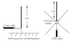
A ground plane antenna is essentially one half of a dipole mounted vertically. The term monopole is also used to describe this antenna. The earth ground below the antenna, a conducting surface a least λ/4 in radius or a pattern of λ/4 conductors called radials, makes up the other half of the antenna (Fig. 5).
If the antenna is connected to a good earth ground, it is called a Marconi antenna. The ground structure serves as the other λ/4 half of the antenna. If the ground plane is adequately sized and conductive, the performance of the ground plane is equivalent to a vertically mounted dipole.
The length of a quarter-wave vertical is:
λ/4 = 246 K/fMHz
The K factor is smaller than 0.95 for verticals, which are usually made with wider tubing.
The feedpoint impedance is one half that of a dipole or about 36 Ω. The actual figure depends upon height above the ground. Like the dipole, the ground plane is resonant and typically has a reactive component to its primary impedance. The most common transmission line is 50-Ω coax, as it is a relatively good match to the antenna impedance with an SWR below 2:1.
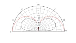
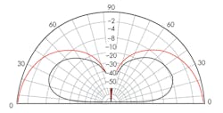
The ground plane antenna is omnidirectional. The horizontal radiation pattern is a circle where the antenna radiates equally well in all directions. Figure 6 shows the vertical radiation pattern. Compared to the dipole’s vertical radiation pattern, the ground plane has a lower angle of radiation, giving it a longer-range propagation advantage at frequencies below about 50 MHz.
Summary
Virtually all other antennas in common usage are variations of the dipole or ground plane antennas. For example, a Yagi-Uda antenna adds parasitic elements like a director and/or reflector to a dipole to increase its gain and directionality. Multiple dipoles can be stacked vertically or arranged in various arrays that greatly increases gain. UHF bowtie TV antennas and PCB meanderline antennas used in some wireless devices are dipole variations. Patch (microstrip) and slot antennas used at microwave frequencies are also dipole derivatives.
In addition, two or more ground plane vertical antennas can be arranged to produce a more directional antenna with gain. For example, a directional AM radio station uses two or more towers to direct a strong signal in one direction while suppressing it in another.
References
American Radio Relay League, The ARRL Antenna Book, 1997-98.
American Radio Relay League, The ARRL Handbook for Radio Communications, 2003.
Bruno Delorme, Antennas and Site Engineering for Mobile Radio Networks, Artech House, 2013.
William Orr, Radio Handbook, 22nd edition, Howard W. Sams & Co. Inc., 1981.
Standing Wave Ratio
Standing waves are voltage and current distribution patterns along a transmission line. If the characteristic impedance (Zo) of the line matches the generator (transmitter) output impedance and the antenna load, the voltage and current along the line is constant. With impedance matched, maximum power transfer occurs.
If the antenna load is not matched to the line impedance, not all of the transmitted power is absorbed by the load. Any power not absorbed by the antenna is reflected back down the line, interfering with the forward signal and producing variations of current and voltage along the line. These variations are the standing waves.
The measure of this mismatch is the standing wave ratio (SWR). SWR is usually expressed as a ratio of maximum and minimum values of forward and reverse current or voltage values along the line:
SWR = Imax/Imin = Vmax/Vmin
Another simpler way to express SWR is as the ratio of the transmission line characteristic impedance (Zo) to the antenna impedance (R):
SWR = Zo/R or R/Zo
depending on which impedance is greater.
The ideal SWR is 1:1. An SWR of 2 to 1 indicates a reflected power of 10%, meaning that 90% of the transmitted power gets to the antenna. An SWR of 2:1 is generally regarded as the maximum allowable for the most efficient system operation.
This file type includes high resolution graphics and schematics.
>> Website Resources
.. >> Library: TechXchange
.. .. >> TechXchange: Antenna Design 101
About the Author

Lou Frenzel
Technical Contributing Editor
Lou Frenzel is a Contributing Technology Editor for Electronic Design Magazine where he writes articles and the blog Communique and other online material on the wireless, networking, and communications sectors. Lou interviews executives and engineers, attends conferences, and researches multiple areas. Lou has been writing in some capacity for ED since 2000.
Lou has 25+ years experience in the electronics industry as an engineer and manager. He has held VP level positions with Heathkit, McGraw Hill, and has 9 years of college teaching experience. Lou holds a bachelor’s degree from the University of Houston and a master’s degree from the University of Maryland. He is author of 28 books on computer and electronic subjects and lives in Bulverde, TX with his wife Joan. His website is www.loufrenzel.com.
