Buck-Boost Voltage Conversion, the Quiet Way
What you'll learn:
- Details of the 4-switch buck-boost architecture.
- What is Silent Switcher technology?
In many applications, voltages require upward and downward conversion. One example would be if an input voltage range of 6 to 24 V is available, and 12 V would be generated from it. Classical wide-range power supplies must be capable of such voltage conversions.
Different voltage-conversion architectures are capable of voltage conversion upward and downward. These are transformer-based topologies such as flyback regulators, a single-ended primary inductor converter (SEPIC) topology, and a 4-switch buck-boost topology.
The 4-Switch Buck-Boost
A 4-switch buck-boost is a very elegant architecture. Four switches are required here, but only one inductor is needed. Figure 1 shows the circuit topology.
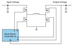
The coil is always controlled by the four switches in such a way that it results in a buck switching regulator converting downwards or a boost switching regulator converting upwards. Conversion efficiency is high and the application of this type of circuit is quite simple.
Download the PDF of this article, and check out the TechXchange for similar articles and videos


A switch-mode buck-boost converter works with a certain switching frequency and generates pulsed currents on internal traces of the voltage converter. These are located on the input side in buck mode when the input voltage is higher than the desired output voltage, or on the output side in boost mode when the input voltage is lower than the desired output voltage. These pulsed currents cause a pulsed magnetic field, generating electromagnetic interference (EMI).
Implementing Silent Switcher Technology
Silent Switcher technology has been available to design switch-mode power converters with very good electromagnetic-compatibility (EMC) behavior. This technique divides the pulsed currents into two conduction paths, each with a high level of symmetry. This halves the amplitude of the pulsed currents and the symmetry largely cancels out the magnetic fields generated.
Figure 2 illustrates the application of this technique to buck-boost controllers. Red shows the paths of the pulsed currents, whose magnetic fields cancel each other out by a symmetrical arrangement.
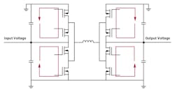
Eight switching transistors are shown in Figure 2. A buck-boost circuit based on Silent Switcher technology requires only four switches, just like a conventional buck-boost topology. The additional switches in Figure 2 are drawn to make the symmetrically pulsed current paths recognizable.
With the combination of a buck-boost regulator and Silent Switcher technology, it’s now possible to develop combined up and downconverters with very good EMC behavior. For the best EMC behavior, there are regulators with integrated decoupling capacitors, referred to as Silent Switcher 2 regulators.
These capacitors from Figure 2 are already integrated into devices such as the LT8350S together with the integrated circuit. This diminishes the parasitic effects in the paths of the pulsed currents and thus reduces radiated emissions even further compared to devices with external decoupling capacitors. One device available with external coupling capacitors is the LT8350.
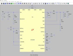
Figure 3 presents a circuit with an LT8350S buck-boost switching regulator. This device can carry up to 6-A switch current and has an input voltage range of 3 to 40 V. To reduce the generated EMI even further, you can use spread-spectrum frequency modulation (SSFM). The circuit in Figure illustrates the LTspice simulation model with external circuitry.
Conclusion
Buck-boost switching regulators are suitable for voltage-converter circuits that must convert voltages up and down. New integrated circuits from Analog Devices, such as the LT8350S, enable developers to execute this topology using Silent Switcher technology to design a switch-mode voltage converter with a very high EMC.
Download the PDF of this article, and check out the TechXchange for similar articles and videos
About the Author

Frederik Dostal
Power-Management Technical Expert
Frederik Dostal is a power-management expert with more than 20 years of experience in this industry. After his studies of microelectronics at the University of Erlangen, Germany, he joined National Semiconductor in 2001, where he worked as a field applications engineer, gaining a lot of experience in implementing power-management solutions in customer projects. During his time at National, he also spent four years in Phoenix, Arizona (USA), working on switch-mode power supplies as an applications engineer.
In 2009, he joined Analog Devices, where since then he held a variety of positions working for the product line and European technical support, and currently brings in his broad design and application knowledge as a power-management expert. Frederik works in the ADI office in Munich, Germany.
Also check out my: