How to Accurately Estimate IC Junction Temperature

Accurately estimating the junction temperature of a semiconductor device is essential for ensuring its reliability, performance, and longevity. Junction temperature has a direct influence on the efficiency, stability, and safety of electronic components.
This article presents techniques for estimating junction temperature, with a focus on utilizing thermal-resistance and thermal-characterization parameters. By following these techniques, engineers can implement effective thermal-management strategies, enhance device performance, and mitigate the risk of overheating-related failures.
Furthermore, the article details fundamental thermal parameters, highlights the key differences between thermal-resistance and thermal-characterization parameters, and introduces practical methods for estimating junction temperature. Also included are case studies to validate the accuracy of these approaches.
Understanding thermal-resistance and -characterization parameters is crucial for evaluating and comparing the thermal performance of electronic packages. These parameters play a key role in effective thermal management and accurate junction temperature estimation. Table 1 shows an overview of the five primary thermal parameters.
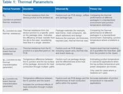
Thermal-Resistance vs. Thermal-Characterization Parameters
Thermal-resistance (θ) and thermal-characterization (ψ) parameters are often confused because they both relate to the thermal performance of electronic packages and involve similar concepts of heat dissipation and temperature differences. However, they serve different purposes and are derived under different conditions.
Thermal resistance, which measures the temperature difference between two points (for example, junction to ambient, junction to case) divided by the power dissipation, is highly dependent on specific conditions like PCB design and airflow. It typically considers a single dominant path of heat flow, making it useful for comparing the thermal performance of different packages and designing cooling solutions.
Thermal-characterization parameters measure the temperature difference between the junction and a specific point (for example, top of the package, board) divided by the power dissipation, considering the combined effect of various heat conduction paths. These parameters depend less on specific conditions, providing more accurate junction temperature estimations in real-world applications.
>>Download the PDF of this article

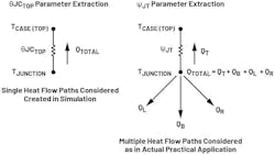
As an example, the junction-to-case (top) thermal-resistance parameter extraction considers all of the package losses to be dissipated through the top side of the package with heat flowing through a single dominant path. The parameters are extracted through simulation and, hence, a condition is created in simulation where they force all of the heat to be dissipated from the top side. This would not occur in a real-world application as heat would be dissipated through different paths in the IC.
On the other hand, the junction-to-case (top) thermal-characterization parameter is derived by considering that, for losses occurring in the IC, only a portion of the heat flows through the top of the package. It accounts for all possible heat-flow paths as they occur in real-world conditions, making it more suitable for estimating junction temperature in practical applications.
Figure 1 provides a simplified illustration of the difference in the heat-flow path for the extraction of these two parameters. Note that this diagram is intended for ease of understanding and doesn’t accurately depict the actual parameter extraction process nor the precise heat-flow path inside the package.
The confusion between these two metrics arises because both involve temperature differences and power dissipation, but they’re applied in different contexts and have distinct dependencies. Understanding these differences is critical for accurate thermal estimation and management.
Techniques for Junction Temperature Estimation
Multiple techniques can be used to estimate the package junction temperature. It’s critical to use the right thermal parameter to ensure accurate temperature estimation. Below are the two dominant methodologies that can be easily applied on the experimental setup for junction temperature estimation.
Method 1: Using Junction-to-Ambient Thermal Resistance (θJA)
Description
It’s a good method for getting a ballpark figure of junction temperature without the need of any specialized equipment. Essentially, it offers an idea of the losses in the package.
Requirements
- The θJA value of the package for the specific PCB under test.
- Ambient temperature of operation and accurate losses in the package.
Equation

Challenges
- The θJA value depends greatly on PCB design and airflow, which can lead to inaccuracies if not properly accounted for.
- Accurate measurement of ambient temperature and IC losses is another critical aspect.
Method 2: Using Junction-to-Case (Top) Thermal Characterization (ψJT)
Description
This method is accurate in estimating junction temperature but needs additional equipment to measure the package case temperature. It can’t be used to estimate junction temperature when a heatsink is employed on the package.
Requirements
- The ψJT value of the package for the PCB under test.
- Accurate measurement of the case top temperature and power dissipation of the package.
Techniques for Case Temperature Measurement
Two of the commonly used methods for package case temperature measurement are:
- Using a thermal camera: A thermal camera can be employed to observe the case temperature. This method is suitable for room temperature measurements. Accurate measurement depends on thermal camera accuracy as well as package losses.
- Using a thermocouple: A thermocouple can be attached to the package case top to measure the case temperature. This method is suitable for measurement at all temperatures, especially when the package needs to be placed in a thermal chamber. Accurate measurement primarily depends on the thermocouple and multimeter used.
Equation

Challenges
- Accurate measurement of the package case temperature is critical for precise junction temperature estimation.
- Attaching a thermocouple to the package case top for temperature measurement can be challenging.
Method Verification: Case Studies
The two methods discussed in this article are verified through bench validation. To test the accuracy of the measurement, the MAX25255 is employed, which features a temperature sensor pin to monitor the IC die junction temperature. This provides a reference point for the actual junction temperature of the IC and how accurately each method estimates the junction temperature.
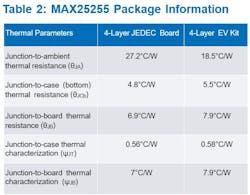
The different thermal parameters for the IC package for both the JEDEC board and EV kit are presented in Table 2. In our tests, we use the 4-layer MAX25255 EV kit for bench validation.
The operating condition for the test case is as follows:
- VIN = 12 V, VOUT = 3.3 V, IOUT = 8 A, fsw = 2,100 kHz, Tamb = 25°C
- Efficiency = 92.3%, IC losses = 1.7 W
- Die junction temperature (as measured by the TEMP pin) = 57.3°C
The different techniques are used to estimate the junction temperature to see how well they match to the actual die temperature.
Case 1: Using θJA
No specialized equipment is needed to calculate the package junction temperature for this method, which reduces the chances of measurement error due to wrong equipment calibration. Simply equate the different parameters in the equation to calculate the junction temperature. For the IC under test, the estimated junction temperature with this method is shown in Equation 3:

The junction temperature estimated here is 56.45°C, which is close to the actual junction temperature measured by the TEMP pin. The error in measurement is about 0.85°C (1.5%). The accurate measurement of ambient temperature and IC losses is critical here to minimize the error in junction temperature estimation. For example, even miscalculating the IC losses by 0.1 W would result in the junction temperature varying by 1.85°C (3.3%).
Case 2: Using ψJT Along with a Thermal Camera for Case Measurement
For this method, a thermal camera is used to measure the IC case top temperature. The thermal camera is an E60BX, which has an accuracy of ±2°C or ±2% (whichever is greater). Allow the converter to operate for 15 to 20 minutes to ensure the IC junction temperature is stable. The maximum case temperature captured for the IC is shown in Figure 2.
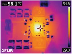
The case temperature measured by the thermal camera is 56.1°C. Equation 4 is used to calculate the junction temperature:

The junction temperature estimated here is 57.09°C, which is very close to the actual junction temperature measured by the TEMP pin. The error in measurement is about 0.21°C — around 0.37% — the error within the accuracy of the thermal camera used for measurement. Estimating the case temperature accurately is more critical than IC loss calculation. For example, even if the IC loss calculation is off by 0.5 W, the junction temperature measurement would be off by 0.29°C/W (0.5%). This is a major advantage of using ψJT over θJA.
Case 3: Using ψJT Along with a Thermocouple
Compared to Case 2, this method uses a thermocouple to measure the package case temperature. A suitable thermocouple needs to be selected based on application specifications. In this case, a Type K thermocouple is selected, which has an accuracy of 2.2°C or 0.75% (whichever is greater).
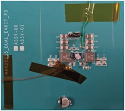
Attaching the thermocouple to the package case is critical to ensure proper measurement — either a thermal paste or thermal glue can be used. Ensure the thermal paste or glue is rated for a temperature higher than what’s needed for the package test. In this case, thermal compound TC3-1G is utilized. Attach the thermocouple to the top of the IC using thermal paste to ensure good thermal contact (Fig. 3).
The thermocouple is connected to a Fluke 52 II thermometer, which has an accuracy of ±[0.05% + 0.3°C]. Allow the converter to operate for 15 to 20 minutes to ensure the IC junction temperature is stable and take the reading on the thermometer. In this case, the thermometer reading was 58°C. Equation 5 is used to calculate the junction temperature:

The junction temperature estimated here is 58.98°C, which isn’t as accurate as the previous two techniques. The error in measurement is about 1.68°C — around 2.93%. The reason for the increased case temperature measurement error is due to the addition of equipment involved in this technique (thermocouple, thermal paste, and thermometer). It’s still within the combined measurement accuracy of different equipment involved. An advantage of this technique is that it can be used to estimate the junction temperature when the package is placed in the thermal chamber as well.
The three case studies validate the discussed package junction temperature estimation techniques. While using θJA offers a good method to get a ballpark figure without specialized equipment, ψJT provides a more accurate estimation. The parameters offer a more precise estimation of junction temperature in real-world applications compared to θJA, which depends greatly on PCB design.
A good example to highlight this difference is to compare the values for the MAX25255’s θJA and ψJT for the JEDEC board and EV kit in Table 2. Note the variation in θJA for the two boards is close to 9°C/W, whereas ψJT only varies by 0.02°C/W.
In summary, the techniques discussed in this article might not be able to determine the package temperature with absolute precision. However, with a thorough understanding of thermal metrics and careful selection of estimation techniques, we can improve the accuracy of thermal measurements.
>>Download the PDF of this article
About the Author
Ankul Gupta
Senior Engineer, Analog Devices Inc.
Ankul Gupta a senior engineer at Analog Devices in the automotive power group based in Chandler, Arizona. He joined ADI in 2022. Ankul received his M.S. and Ph.D. degrees in electrical engineering from Arizona State University, Tempe, Ariz., in 2019 and 2022, respectively.
Comment About the Article
To join the conversation, and become an exclusive member of Electronic Design, create an account today!

Leaders relevant to this article: