How to Control Brushless Motors (Part 1)
What you'll learn:
- The design of different three-phase brushless DC motors and how they generate torque.
- How magnetics, construction, and other factors impact torque, speed, and smoothness in BLDC motors.
- General introduction to the control architecture for BLDC motors, including the use of PWM-based switching.
Brushless DC motors, also called brushless motors or BLDC motors, are popular for high-reliability and high-performance motion control. They don’t use mechanical brushes that can generate particulates and wear out; instead, they’re commutated electronically. The advantages of BLDC motors are high torque output, high spin rate, and brushless operation. However, their main drawback is cost relative to DC brushed or stepper motors
BLDC motors can be divided into two major motor groups: rotary BLDC motors and linear BLDC motors. There are further sub-divisions, specifically in the realm of rotary motors, which can be differentiated by inner or outer rotor construction as well as axial-flux or radial-flux designs. Inner-rotor BLDC motors break down into the interior permanent magnet (IPM) type or the surface-magnet type. Finally, iron core construction methods distinguish between slotted BLDC motors and slot-less BLDC motors.
Most of these variations have little impact on the techniques used for motor control, but they can have a significant impact on important performance characteristics, including the torque-to-weight output, smoothness, maximum acceleration rate, and top speed.
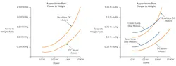
Where do three-phase brushless motors fit within the larger range of positioning motor choices? Figure 1 shows two graphs comparing various motor types in two key performance metrics: the ratio of power output to weight and the ratio of torque output to weight. For a given application, one of these factors is usually more important than the other. However, they’re actually related because power is defined as torque times the spin rate.
The Magnetics Matter in Brushless DC Motors
Determining what happens inside the motor and how brushless motors generate torque provides a foundation for understanding how various BLDC control techniques work. The diagram in Figure 2 shows the magnetic fields of the brushless motor’s rotor and stator looking down the rotation axis of the motor and projected onto an XY plane.
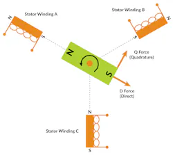
Torque is generated by the interaction of the magnetic fields created by permanent magnets in the rotor and the windings in the stator. Each of the stator windings (referred to as windings A, B, and C in Figure 2) generate their own magnetic field vector oriented 120 degrees apart. These individual vectors are called winding current space vectors.
Because they all share a common iron core, the net direction of the stator’s magnetic field can be thought of as a single vector consisting of the sum of the three individual winding vectors. This summed vector is called the stator current space vector.
>>Download the PDF of this article from Performance Motion Devices
In Figure 2, the central green magnet is the rotor and can be thought of as a simple bar magnet with a north and south pole. Depending on how the individual stator windings are driven, they can create force that’s perpendicular to the direction of the magnetic rotor field, or they can create force which is parallel to the rotor magnetic field. These two different kinds of force are known as the quadrature (Q) and direct (D) forces, respectively.
How do the three magnetic fields generated by the stator windings combine to form a single stator current space vector? The answer is that the net stator vector has a direction and magnitude equal to the sum of the individual winding current space vectors (Fig. 3). Ia, Ib, and Ic are the magnetic fields created by current Ia in the A winding, current Ib in the B winding, and current Ic in the C winding.
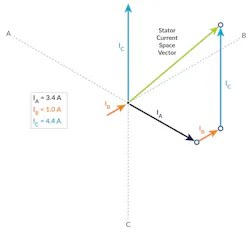
These three magnetic vectors, which are oriented 120 degrees apart from each other, have a different magnitude owing to the different current flowing through their winding. In the example above, Ia comes with a current of 3.4 A, Ib with current of 1.0 A, and Ic with 4.4 A. They’re drawn in an XY plane, and the net vector is created by joining the individual vectors “head to tail,” resulting in the single net stator magnetic vector visible in green (Fig. 3, again).
When the angle of the rotor’s magnetic field and the stator’s magnetic field are perpendicular, the Q (rotation generating) force is at its maximum and the D (non-rotation generating) force is zero. Conversely, if the rotor magnetic field and net stator magnetic field are parallel, the Q force is zero and the D force is at its maximum. Only the perpendicular Q force generates useful rotational torque. The parallel D force serves to compress the rotor, which generates no rotational torque.
To generate maximum torque, the controller manipulates the stator vector angle so that it always points perpendicular to the rotor magnetic angle. This process is called commutation — the controller achieves this by inputting sensor signals from the motor indicating the position of the rotor, which allows the controller to adjust the stator magnetic angle as the rotor rotates. More on this will come in later articles focused on commutation.
The Importance of Motor Poles in BLDC Motors
A key factor in BLDC motor construction is the notion of motor poles. Brushless motors can be wound in such a way that a single 360-degree mechanical rotation is driven by a single 360-degree electrical rotation, by two 360-degree electrical rotations, or by many electrical rotations. Note that a 360-degree electrical rotation here means a 360-degree rotation of the stator’s magnetic field angle.
A motor that makes one full mechanical rotation for one full stator angle rotation is a two-pole motor (traversing a north pole and a south pole). Two-pole motors are sometimes also labeled as one-pole-pair motors. When a single mechanical rotation results from two electrical rotations, this is a four-pole motor. BLDC motors can have 2, 4, 6, 12, or other even numbers of poles. In all cases, the number of pole pairs is half the number of poles.
What are the pros and cons of different numbers of poles in BLDC motor? Broadly speaking, higher pole counts give BLDC motors higher torque output but result in lower top-end rotational speed. Many motor design factors affect both these metrics, but other details being equal, that’s the primary functional effect of differences in pole count.
The Differences Between Rotary and Linear BLDC Motors
So far, we’ve only talked about rotary motors, but all of the principles discussed above can also be applied to linear brushless motors.
How is a linear BLDC motor constructed? Figure 4 shows how a linear motor compares to a rotary motor. The linear version of the brushless DC motor is essentially an unwrapped rotary motor. They both have a stator — the part that houses the coils. And they both have a rotor — the part that contains the permanent magnets.
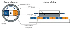
Note that rotor is a confusing term for a linear motor since it doesn’t rotate. Nevertheless, we will use this term because there’s no other standard accepted term for this part of the linear motor.
Control of the linear motor from the perspective of setting the stator angle is similar to rotary brushless motors. Linear motors use commutation to drive the stator windings with a vector angle that results in maximization of the useful Q force and minimization of the non-useful D force.
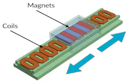
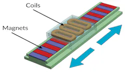
With linear BLDC motors, two different configurations of the stator and rotor are possible, one where the stator (the part with the coils) is stationary and the rotor (the part with the magnets) moves, and the opposite configuration where the stator moves and the rotor is stationary (Figs. 5 and 6).
A variation of the “track” layout scheme for linear BLDC motors uses a rod. The rod contains alternating north/south-oriented magnets and therefore functions as the rotor. Once again, either the rotor (the rod) can move with the stator staying stationary or, more commonly, the rotor can be stationary with the stator traveling across it (Fig. 7).
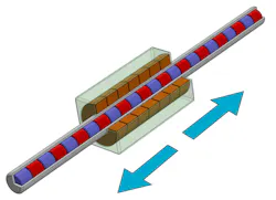
Whatever arrangement is used, the linear brushless motor is a popular choice in applications that demand high reliability and fast response time. While significantly more expensive than actuators that convert motor rotation into linear motion (using mechanisms such as ball screws or pinion gears), they’re capable of much higher positioning accuracies. This is because mechanisms that convert rotary motion into linear motion inevitably introduce backlash and compliance, lowering final positioning accuracy.
One factor pushing the adoption of linear BLDC motors is the availability of high-resolution encoders at relatively low prices. New encoder types such as sin/cos encoders and BiSS-C serial encoder data connections have become available. When combined with advanced signal processing electronics, they make it possible for linear stages and XY stages to provide extraordinary positioning resolution of nanometers or even picometers.
The Building Blocks of BLDC Motor Controllers
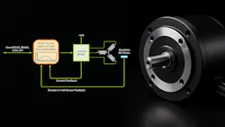
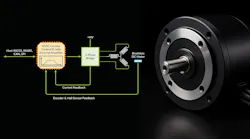
With this general introduction to BLDC motors complete, we can dive into the subject at the heart of this series: How to control brushless motors. BLDC motors are “multi-phase” devices, meaning multiple motor coils in the motor stator are electrically energized to create rotation. Figure 8 shows the control architecture of a three-phase brushless motor controller.
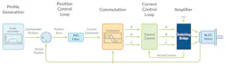
For position-control applications, a position control loop generates a current command that minimizes the difference between the desired (commanded) position and the actual (measured) motor position. Some applications require only velocity control rather than position control, in which case the controller uses a velocity servo loop instead of a position loop.
In either instance, the output of this loop is a desired current command, which can be interpreted as the desired amount of motor torque generation.
The current command is then commutated, meaning the total desired current is distributed into separate commands for each of the three motor windings. Various commutation schemes exist, depending on the position sensor used and the desired levels of efficiency and smoothness. Next, a current control loop measures the current flowing through each motor winding and adjusts the applied voltage so that the actual current closely matches the commanded current.
Finally, an amplifier applies the voltage commands to each motor winding. Today, most amplifiers use a pulse-width-modulation (PWM)-based switching bridge design due to its very high efficiency and ease of control. However, in electronic systems requiring ultra-low electromagnetic interference (EMI), linear amplifiers may still be used.
Across BLDC motor controllers, significant variations of this architecture exist. For example, some controllers don’t employ active current control of the motor windings, and in non-positioning applications, some omit position sensors entirely — a technique known as sensorless control.
The next part of this series will provide a more detailed look at each of the motion controller sections highlighted above.
>>Download the PDF of this article from Performance Motion Devices
About the Author

Chuck Lewin
Chuck Lewin, Founder and CEO, Performance Motion Devices Inc.
Chuck Lewin is Founder and CEO of Performance Motion Devices Inc. In 1992, Lewin developed a motion control on an IC technology to found PMD. In less than a year, the company released its first IC multi-axis motion processor with functions previously only on board-level motion control products. In 2024, the company introduced its ION/CME N-Series PCB-mountable drive, delivering integrated motion control, network connectivity, and power amplification in a single module.
Today, the company manufactures motion controls for servo and step motors with CAN, serial, SPI, and Ethernet communications—and capable of S-curves, synchronized multi-axis contouring, precision torque control, field-oriented control, and many other advanced capabilities.
Comment About the Article
To join the conversation, and become an exclusive member of Electronic Design, create an account today!

Leaders relevant to this article: