How to Control Brushless Motors (Part 2): Position-Control Loops
What you'll learn:
- The importance of motor trajectory profiles and how they’re used in brushless DC (BLDC) motor control to minimize vibration and smooth out other performance issues.
- Why the PID loop is the most widely used position-control method in brushless DC servo systems and how it determines the position of the motor.
- How to tune a position-control loop using practical approaches such as step-response testing to achieve stable and well-damped system performance.
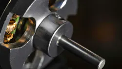
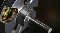
Brushless DC (BLDC) motors are being widely adopted in high-performance motion control. Unlike brushed motors, they do not rely on mechanical brushes that tend to wear out over time. Instead, they use electronic commutation to control torque and speed, resulting in higher efficiency, greater power density, and longer lifespan.
These advantages come with tighter control requirements. Such motors depend on real-time, low-latency control loops to achieve stable, quick-response movement.
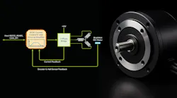
Owing to that, motor controllers play a central role in system performance, particularly in industrial automation, ranging from humanoid-robot joints to high-speed pick-and-place systems assembling the electronics that go inside them. In any case, motor control is typically divided into several functions that must be carefully coordinated to maintain smooth, balanced motion, as outlined in Figure 1.
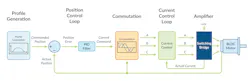
These functions form a hierarchy in which the control loops further up the line provide the inputs to those further down the line. For position-control applications, a position-control loop compares the desired motor position with the actual, measured position. Using a predefined motion profile, it outputs a desired current command, which corresponds to the amount of torque the motor needs to produce to put itself in the right position.
The system then commutates the current command by distributing it across the motor’s windings to enable efficient, smooth operation. A current-control loop then measures the actual current in each winding and adjusts the applied voltage to match the commanded current as closely as possible. In most cases, pulse-width modulation (PWM) switching bridges are used to apply these voltages to the motor.
While the current control and PWM switching play the most direct role in driving brushless DC motors, the motion profile and position-control loop can’t be overlooked. They help optimize overall performance by minimizing vibration in the motor and smoothing out other performance issues. This article zooms in on these aspects of motor control; commutation and current control will be covered later in this series.
Brushless Motor Trajectory Profiles
The motion profiles used with BLDC motors generally aren’t different from those used with brushed DC or stepper motors. The diagrams below show the velocity and acceleration profiles for two of the most popular motor-trajectory profiles: a point-to-point s-curve profile and a point-to-point trajectory profile. These are the workhorses for a wide range of machines, including laboratory automation, packaging equipment, industrial equipment, and more (Fig. 2).
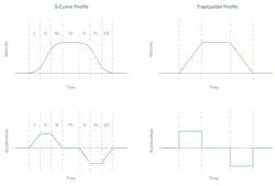
Both of these trajectories are widely used with BLDC motors in position-control applications. If the load is susceptible to mechanical resonance issues, the s-curve profile is typically used because it avoids abrupt changes in acceleration that may induce these resonances in the load.
In other situations, a trapezoidal profile is the preferred choice. It avoids the increase in transfer time that occurs in the “S” segments of the s-curve profile, which are marked I and VII in Figure 2.
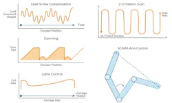
In addition to these common point-to-point profiles, there’s a wide range of other industry- and application-specific motor profiles. These profiles can be single- or multi-axis, and the process of generating them can be synchronized to an external feed rate signal such as a CAM profile. Some motion profiles have complex shapes that perform inverse kinematic transforms to control selective compliance assembly robot arms (SCARA) or other types of robots.
>>Download the PDF of this article, and check out Part 1 of this series from Performance Motion Devices
In addition to generation of the desired profile shape, some motion controllers also support table-based position compensation schemes such as lead-screw mapping, compliance compensation, and encoder INL correction. These involve determining the position output of the uncompensated system and then creating a correction table that uses the commanded position as a lookup to retrieve the correction value.
Whether simple or complex, the motion profiles used with brushless DC motors are generally similar to those employed with brushed DC motors or stepper motors. Nevertheless, trajectory generation is a very important subject in motion control, and the figures below are intended to outline the many applications where it plays a central role (Fig. 3).
For further reading on the topic, check out these resources:
- S-Curve Motion Profiles – Vital for Optimizing Machine Performance
- Motion Kinematics
- CAM Profiling
- Delta Robot Control
- High Speed Pick and Place
Position Control of Brushless DC Motors
Outlined in Figure 4 is a representative position-control loop flow diagram for brushless DC motors. Although several types of position servo loops are available to engineers, the overwhelming favorite is the PID loop.
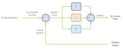
In the PID position loop, a desired position is provided by the profile generator and compared with the actual position of the motor as measured by an encoder to generate a position error. Signals from Hall-based position sensors can also be used to provide position feedback. However, the positioning resolution of these magnetic sensors will be much lower. In any case, the position error value is then put through a PID filter — short for proportional, integral, derivative — to generate a current command output value.
Note that this same position-control loop can be used for other types of servo motors, such as DC brushed motors. That’s because most of the control elements related to the multiphase nature of BLDC motors are downstream of the position loop.
While the output of the position loop generally flows into a current loop, it can also go to a velocity loop that, in turn, drives a current loop. This arrangement is called a cascaded position/velocity loop. Although it’s a more complicated scheme with more gain value settings, it may outperform the position-only controller in some applications.
In the PID position loop in Figure 4, we should be aware that the “loop” part of the controller is the summing junction in the diagram to the left, where we subtract the actual position from the commanded position to generate a position error value. The PID part of the controller is actually a type of filter called a PID filter. The PID filter takes a stream of position error values as input and generates a stream of commands to a current loop or, in some cases, a velocity loop as output.
To tune a position PID loop, it’s not necessary to know how the PID filter is calculated. However, for reference, the basic equation is below. The PID filter output value as well as its inputs are updated and calculated at each servo-loop update. Modern motion controllers operate with servo-loop update rates anywhere from 1 kHz to as high as 80 kHz, with 5 to 20 kHz being typical for controllers used in motors sized NEMA 17 through NEMA 42.
Outputn = Kp * En + Ki * sum(En) + Kd * (En – En-1)
where:
- En is the current position error value
- En-1 is the previous position error value
- Sum(En) is the sum of En values past and present
Understanding the PID Filter
The main reason the PID position control loop is so popular is that its constituent pieces — the P, the I, and the D — and their impact on motor control can be understood intuitively.
First, the P term is called the proportional term because it provides a proportional restoring correction to the amplifier output command. When presented with the position error, the P term functions like a spring. The larger the position error of the servo motor, the larger the corrective restoring motor command.
The I term is the integral (or integration) term because it integrates, over time, the servo position error. Why would this be useful? Because if only a P (proportional) term is used, it may be difficult to arrive at the exact commanded position due to forces or mechanical issues such as gravity, stiction, motor detents, or other factors. The I term builds up over time and can help get the servo “over the hump” to the final desired position.
Finally, the contribution of the D term is calculated by subtracting the previous position error from the current position error. This has two main practical effects: it delivers a feedforward boost whenever the profile velocity increases or decreases, and it provides a general-purpose drag term, thereby dampening oscillations.
How To Set Position Loop Gain Parameters
Determining appropriate gain settings for a position-control loop is a nuanced task. To keep things simple for now, we will provide a quick overview of a widely used approach: step-response tuning.
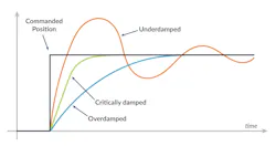
In step-response tuning, the motor controller is subjected to a small, instantaneous change in the commanded position to see what the position loop’s control response will be. The goal is to classify the system’s response as underdamped, critically damped, or overdamped. Figure 5 illustrates these characteristic responses, showing the motor’s actual position as it reacts to a step change in position.
To begin, we will only focus on setting the Kp and Kd values. The initial values should be low, with the Kd setting roughly 10X the Kp setting. At each iteration, we will execute an impulse step move and then view the response. If the response is underdamped, we will lower Kp or increase Kd. If the response is overdamped, we will increase Kp or decrease Kd.
The overall position loop tuning goal is to set the Kp to as high a value as possible while still finding associated Kd values that can create a critically damped response. Higher Kp values will result in more accurate tracking and faster responses to command position changes.
The situation becomes more complicated as the values increase. When the values become more aggressive, it’s common for the axis to begin to “chatter,” even when holding the same position.
Another PID loop setting called the “derivative time” can be a very effective way of eliminating that problem. Derivative time is the period at which the PID loop derivative contribution is calculated. Increasing the derivative time effectively introduces a low-pass filter on the PID loop’s control response. That, in turn, makes it possible to increase the effective Kd damping contribution without increasing noise and chatter.
Once satisfactory values for Kp, Kd, and derivative time have been reached, you can enter a value of Ki (integral gain) to improve tracking accuracy. Typically, Ki settings are 1/10 to 1/2 of the Kp value, but there’s a wide range. Higher Ki settings will increase tracking accuracy during and after the motor move is complete, but they can also reduce overall system stability. So, Ki should be set to the smallest value that still achieves the system goals for final or dynamic tracking accuracy.
For an in-depth discussion on this topic, check out the article, “How To Tune A PID Loop.”
Position PID Loop with Feedforward
The simplified position loop in Figure 4 didn’t include an important control feature called feedforward. Figure 6 adds this feature, showing two feedforward terms: a velocity proportional term called velocity feedforward, and an acceleration proportional term called acceleration feedforward.
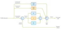
These feedforward terms are accompanied with a gain setting; KVff, and KAff. Introducing these feedforward terms to the control loop is relatively simple: They’re just numerically added to the PID position loop output.
Notice that the contribution of these terms isn’t influenced by anything measured in the actual system, such as the encoder position. Feedforward terms, by definition, are outside the servo loop and depend on knowledge of how the system will react to changes in the desired motion profile or other factors. The better feedforward terms anticipate the torques that the motor will experience as it moves, lessening what the servo loop must do, and thus leading to more accurate and responsive motor performance.
In the real world, several factors don’t allow for perfect feedforward compensation. Load masses are often variable, and motors and mechanisms don’t behave exactly the same, even if built to tight tolerances. So, in adding a torque compensation value, our expectation should be to lower, but not eliminate, the amount of work that the PID loop must do.
How are feedforward gains determined? Although, in theory, a model of the motor and attached mechanics could predict best feedforward gains, most engineers will determine feedforward gain settings by executing trajectory profiles and observing the system’s resultant servo error. Figure 7 shows what these graphs might look like.
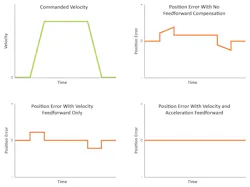
Figure 7 illustrates a hypothetical system response, showing the position error during a trapezoidal profile move with no feedforward compensation applied, velocity feedforward only applied, and both velocity and acceleration feedforward applied. The process of determining the feedforward gains is similar to the iterative step response tuning described earlier, where values are tested and then increased or decreased according to the observed response.
Velocity Control of Brushless Motors
While this article has largely focused on position-based control of BLDC motors, many applications, including pump control, dispensing applications, spindle control, machine tools, and a wide range of other industrial processes, only require velocity control of the motor. In these cases, the motor controller uses a velocity servo loop instead of a position loop.
Figure 8 illustrates a simplified velocity loop diagram. As before, this same control loop can be used for other servo motors such as DC brush motors. In this velocity controller, a desired velocity is input by a profile generator, and an actual velocity is measured and compared to generate a velocity error, which is then put through a PI (proportional, integral) filter to generate a downstream current command to the downstream current loop.
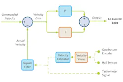
The prevalence of position encoders to measure the motor’s rotor position poses several challenges here. One challenge of operating a velocity loop is generating an accurate measure of the motor’s velocity. This can be seen in Figure 8 by the presence of processing elements when the feedback is a position value. By comparison, tachometer feedback, which provides a direct measure of motor velocity, doesn’t need to go through this special processing.
At high velocity, where the encoder reading may change hundreds of counts per sample time, it can be relatively easy to generate a smoothly varying velocity estimation. But the challenge rears its head at lower velocities, which can drop all the way down to less than one count per servo-loop sample time. At these speeds, filters and other components (in this case, a biquad filter programmed to provide a low-pass filter function) are required to convert the inherently “quantized” cycle-by-cycle position data into a more smoothly varying velocity value.
Similar to position PID loops, the velocity PI loop gain settings are programmable and must be determined by the user for the specific application at hand. Also, similarly to position loops, velocity loops may implement feedforward terms to improve tracking during acceleration and deceleration or when other machine operating conditions generate a predictable impact on the velocity.
Finally, two other BLDC motor-control modes don’t use a velocity loop but effectively provide velocity control: sensorless control and voltage-based control. We will discuss both modes a bit later in the series.
In the next article, we will continue to run through the different components of a brushless DC motor controller, focusing on one of the most important concepts: commutation.
>>Download the PDF of this article, and check out Part 1 of this series from Performance Motion Devices
About the Author

Chuck Lewin
Chuck Lewin, Founder and CEO, Performance Motion Devices Inc.
Chuck Lewin is Founder and CEO of Performance Motion Devices Inc. In 1992, Lewin developed a motion control on an IC technology to found PMD. In less than a year, the company released its first IC multi-axis motion processor with functions previously only on board-level motion control products. In 2024, the company introduced its ION/CME N-Series PCB-mountable drive, delivering integrated motion control, network connectivity, and power amplification in a single module.
Today, the company manufactures motion controls for servo and step motors with CAN, serial, SPI, and Ethernet communications—and capable of S-curves, synchronized multi-axis contouring, precision torque control, field-oriented control, and many other advanced capabilities.
Comment About the Article
To join the conversation, and become an exclusive member of Electronic Design, create an account today!

Leaders relevant to this article: