Designing for Safety and Immunity (Part 1): Safety Isolation Principles in Industrial PC Interfaces
What you’ll learn:
- How to design industrial PCs to meet electromagnetic compatibility (EMC) standards.
- How to determine creepage, clearance, and isolation voltage requirements for safety applications.

As industrial workloads become more demanding, the need for stronger computing platforms, such as industrial PCs (IPCs), continues to rise. However, these compact, high-performance systems must meet stringent safety requirements, often driven by the user-accessible interfaces that connect to third-party equipment and cables.
This article, Part 1 of a two-part series, outlines the safety and electromagnetic compatibility (EMC) standards that commonly drive interface isolation requirements in IPCs. Using IEC 61010-1 and IEC 60601-1 as the main references, learn how to select insulation type and determine creepage, clearance, and dielectric withstand requirements to support reliable, plug-and-play, cost-efficient architectures.
IPCs and the Move to Modularity
Modern IPCs are compact, modular computing systems designed to run specific industrial tasks. They’re often fanless and ruggedized to operate reliably in harsh environments, but active-cooling variants also exist for higher-power CPUs/GPUs.
Thanks to increasing computational performance and the availability of AI-accelerated platforms, IPCs are gaining adoption in factory and edge automation, sometimes complementing or replacing programmable logic controllers (PLCs) for advanced control, vision, analytics, and robotics.
A key trend in this sector is a shift toward modular design, with manufacturers using computer-on-module (COM) and system-on-module (SoM) solutions like NVIDIA Jetson or COM Express modules based on Intel/AMD. This simplifies development of custom IPCs: A tailored carrier is paired with an off-the-shelf compute module for targeted workloads. Modular systems offer flexible mounting, better repairability, and simpler integration of specialized components.
SoM/COM module components:
- CPU/system-on-chip (SoC): Often x86 or Arm architecture, which may include an integrated GPU.
- RAM and storage: High-speed memory (DDRx) and solid-state storage (SSD/NVMe).
Carrier board components:
- Industrial I/O interfaces: USB, RS-485, video inputs, and digital/analog I/O with isolation.
- Communication modules: Ethernet (MAC + PHY), Wi-Fi/Bluetooth, cellular (LTE/5G)
- High‑speed expansion: PCIe, SATA connectivity, and fieldbus/motion cards (EtherCAT, PROFINET, etc.)
- System power management and housekeeping: Voltage regulators, transient protection, and supervisors.

This modular approach leaves the engineer with the critical task of handling the carrier board’s power, connectors, and industrial I/O interfaces where the system meets the harsh physical world. Rather than simply replacing existing automation, IPCs are often deployed to augment the factory floor.
Typical IPC workloads include control, monitoring, HMI/SCADA visualization, machine vision, robotics, data collection, and edge analytics and gateways. Representative applications include:
- Factory automation: Advanced control, PLC replacement in soft-PLC architectures, robotics, motion control, machine vision, and quality inspection
- Transportation: Rail systems, vehicles (buses, trucks), passenger information systems, and predictive maintenance
- Energy and utilities: Solar/wind plant controllers, substation automation, condition monitoring, and edge data aggregation
- Healthcare: Patient monitoring gateways, imaging system controllers, device connectivity, and cybersecurity gateways
- Smart cities and Internet of Things (IoT): Surveillance and video analytics, edge gateways, traffic management, environmental monitoring.
Safety and EMC Considerations Driving Isolation Requirements in IPC Designs
Depending on the end application, IPCs must meet critical system protection and design requirements to comply with safety and electromagnetic immunity (EMI) standards. User-accessible interfaces and long external cables are common entry points for hazardous voltage exposure, ground potential differences, surges, and conducted RF disturbances.
As a result, galvanic isolation is a common design technique to help meet separation, fault-containment, and immunity goals while enabling robust plug-and-play interfaces.
Each of the standards below targets specific industry hazards, setting unique thresholds for isolation spacing (creepage/clearance) and dielectric withstand that the IPC interface must meet:
- IEC 60601‑1—Medical electrical equipment: Defines safety requirements for protecting patients and operators. Often drives stringent separation requirements (means of patient protection (MOPP)/means of operator protection (MOOP)) at applied parts and accessible connectors.
- IEC 61010-1/IEC 61010-2-201—Industrial and laboratory equipment: Specifies electrical safety requirements for control, measurement, and laboratory systems.
- IEC 60079-11—intrinsic safety “i” in explosive atmospheres: Requires that circuits located in hazardous areas are energy-limited so they can’t ignite an explosive gas atmosphere through sparks or hot surfaces, even under defined fault conditions. When intrinsic-safety (IS) circuits interface with other IS circuits or with non-IS circuits in the safe area, galvanic isolation is the standard method to maintain the required energy-limiting boundaries.
- IEC 61508—functional safety of electrical/electronic/programmable electronic safety‑related systems: Defines requirements for achieving safety integrity levels (SILs).
While galvanic isolation isn’t mandatory, it’s widely used to prevent fault propagation and support fault exclusion. For example, using two independent channels with galvanic isolation reduces susceptibility to common-cause failures (CCFs) by preventing fault propagation between channels. Beyond meeting safety requirements, IPC interfaces must also satisfy conducted immunity because long external cables and third-party connections provide direct paths for fast transients, surges, and RF disturbances to enter the system. Compliance is judged at the equipment port regardless of whether the interface is galvanically isolated.
Galvanic isolation can nevertheless make it easier to achieve higher immunity by breaking direct-current paths/ground loops and by leveraging isolators with high common-mode transient immunity (CMTI) to prevent common‑mode events from corrupting signals. The specifics of these standards and test methods will be covered in Part 2 of this article series.
For example, the application‑specific EMC standards define required immunity levels and performance criteria for a given equipment type:
- IEC 61326-1: EMC requirements in electrical equipment or measurement, control, and laboratory use
- IEC 61131-2: Functional and EMC requirements for PLCs, IPCs, and industrial control equipment
- IEC 61000-6-2: Generic EMC immunity standard for industrial environments
- IEC 60601-1-2: EMC requirements for medical electrical equipment
General conducted immunity standards (referenced by application‑specific standards):
- IEC 61000-4-4: Electrical fast transient (EFT/burst) immunity tests on power and signal cables
- IEC 61000-4-5: Surge immunity tests (lightning-induced and switching surges) on power and signal cables
- IEC 61000-4-6: Immunity to conducted disturbances induced by radiofrequency fields (often associated with ground-loop and common-mode coupling effects)
The Need for Safety Isolation in I/O Interfaces
IPC manufacturers often integrate safety isolation at external interfaces to protect operators from hazardous voltages, simplify system-level insulation coordination, and enable plug-and-play integration with third-party equipment. This section focuses mainly on safety isolation, whereas functional isolation will be covered in Part 2.
Human Operators Protection
Isolation is critical for protecting human operators against hazardous voltages arising from normal operation or fault conditions.
According to IEC 61010-1, an accessible part is considered hazardous live if the voltage exceeds 50 V RMS AC or 120 V DC under single-fault conditions.
Protection against hazardous live voltages must be ensured both under normal operating conditions and single-fault conditions, defined as conditions in which one means of protection (MOP) is defective or one fault is present that could lead to a hazardous situation.
Meeting these requirements often necessitates the implementation of double insulation (basic insulation + supplementary insulation) or reinforced insulation (Fig. 2).
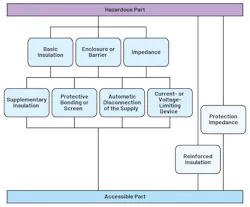
In the following sections, the methods for calculating creepage and clearance requirements for medical and industrial PCs are described, considering the applicable safety standard and system architecture.
System Architecture Optimization and Simplified Integration with Third-Party Equipment
Optimizing System-Level Insulation Diagram
Strategically placing isolation at external interfaces can simplify insulation requirements elsewhere in the system. For example, when a reinforced barrier is implemented at a user-accessible interface, the upstream power supply may require only basic insulation — if the overall architecture ensures that two independent means of protection exist in series along the hazard-to-touch path.
Taken together, these two independent insulation barriers form double insulation, which provides effective protection for the operator against single-fault conditions and hazardous live voltages.
Smart Isolation Architecture for Industrial Front Ends
Similar optimization applies in industrial data-acquisition (DAQ) systems, which require both functional isolation (for level-shifting and high common-mode voltage tolerance) and safety isolation. Rather than implementing reinforced isolation at each measurement channel — which increases size, cost, and complexity — a single reinforced barrier can be placed upstream, separating the DAQ front-end from the rest of the system. Each channel then requires only functional isolation for level-shifting and high-side measurements.
This architecture maintains reinforced isolation at the system level while reducing per-channel complexity and cost. The resulting structure consists of one reinforced isolation barrier at the back of the channel array, complemented by per-channel functional isolation barriers. It achieves safety, level-shifting, and channel-to-channel isolation in a more area‑ and cost‑efficient design.
Plug-and-Play Integration with Commercial Peripherals
Adding safety isolation to the interfaces of an industrial or medical PC (such as HDMI or USB ports) enables the use of off-the-shelf monitors or consumer devices while keeping the overall system compliant with IEC 60601-1 and IEC 61010-1.
This remains true even when the connected equipment itself isn’t compliant with these standards. That’s because external equipment is treated as potentially unsafe and the required protection is implemented internally within the system via an isolation barrier meeting the applicable safety requirements. Such an approach simplifies field integration, supports true plug‑and‑play operation, and improves equipment robustness against human error.
Determination of Creepage, Clearance, and Isolation Voltage Requirements for Safety Applications
Safety standards specify minimum values of clearance, creepage, dielectric withstand (hipot), and constructional requirements for isolation barriers. Values are determined by the insulation type (functional, basic, supplementary, or reinforced) and the rated working conditions.
The following sections detail how to compute the minimum required values of these parameters according to the IEC 60601-1 and IEC 61010-1 safety standards.
Medical PCs (IEC 60601-1): Calculation of Creepage, Clearance, and Isolation Voltage Requirements
Creepage and clearance distances according to IEC 60601-1 depend on the mains supply voltage and the type of insulation (basic or reinforced, also known as 1 MOPP or 2 MOPP). These distances are specified in Table 12 of the standard. For a system connected to a 250-V rms mains supply with a 2 MOPP requirement at the isolated interface, the required creepage and clearance distance is 8 mm (Table 1).

Isolation voltage requirements according to IEC 60601-1 are defined by the dielectric strength test, which specifies a 1-minute test voltage depending on the mains voltage, the circuit classification (mains circuits vs. secondary circuits), and the required insulation level (1 MOPP or 2 MOPP). These requirements are specified in Table 6 of the standard.
For equipment connected to a 250-V RMS mains supply, with a 2 MOPP requirement between the mains part and the accessible or patient-connected circuits, the required dielectric test voltage is 4 kV RMS (1-minute test). For a 1 MOPP requirement, the corresponding test voltage is 1.5 kV RMS (Table 2).

Industrial PCs (IEC 61010-1): Calculation of Creepage, Clearance, and Isolation Voltage
According to IEC 61010-1, creepage and clearance requirements depend on the following parameters: overvoltage category (OVC), rated mains voltage, pollution degree (PD), material group (package or PCB material group), and type of insulation (basic or reinforced). For mains voltages of 150 V RMS or 1,250 V RMS, the applicable creepage and clearance values are defined in Table 4 of IEC 61010-1.
When reinforced insulation is required, the creepage distance is twice the value specified for basic insulation. As an example, consider a system installed in an OVC II, PD II environment, supplied from a 250-V RMS mains voltage, and requiring reinforced insulation at the USB interface. If the insulating material is classified as material group I, the required creepage distance is 3.0 mm, corresponding to twice the 1.5-mm basic insulation requirement. If the material were classified as material group II, the minimum required creepage distance would increase to 4.2 mm (Table 3).

According to IEC 61010-1, the required isolation (dielectric withstand) voltage depends on the following parameters: OVC, rated mains voltage, and type of insulation (basic or reinforced). For equipment installed in an OVC II environment with rated mains voltages up to 300 V, Table 5 of IEC 61010-1 specifies the applicable 1-minute dielectric test voltages. Assuming a 250-V RMS mains supply and a requirement for reinforced insulation at the interface, the minimum required isolation test voltage is 3 kV RMS with 1-minute duration (Table 4).

Conclusion
This article presented common industrial PC architectures and explained why user accessible I/O often becomes the primary driver for safety isolation. Using IEC 60601-1 and IEC 61010-1 as the main references, it provided a practical approach for translating insulation type (basic, supplementary/double, or reinforced; 1 MOPP/2 MOPP where applicable) into concrete interface requirements for creepage, clearance, and dielectric withstand requirements for reliable, plug-and-play system architectures.
In Part 2, we’ll shift from safety-driven insulation coordination to immunity-driven interface design. It will show how EFT/burst, surge, and conducted RF requirements influence protection choices and isolator selection in real end applications with long cables and third-party equipment.
>>Download the PDF of this article
 dreamstime_sorapolujjin_94170105
About the Author
 Riccardo Privitera
Riccardo Privitera
Product Applications Engineer, Analog Devices Inc.
Riccardo Privitera is a product applications engineer at Analog Devices. He holds a B.S. in electronics engineering from Universita’ di Catania and an M.S. in microelectronics engineering from Politecnico di Torino. Currently, he focuses on defining, supporting, and developing high-speed isolated interfaces that use iCoupler technology.
 Prasanthi Yerra
Prasanthi Yerra
Systems Applications Engineer, Analog Devices Inc.
Prasanthi Yerra is a systems applications engineer at Analog Devices, with 7 years of experience in electronic systems development. She holds a master’s degree in electronic engineering from Politecnico di Milano. She began her career as an embedded developer working on IoT projects and later worked as an applications engineer in laser beam scanning technology and isolated products. Currently, she focuses on system applications of precision signal chains and isolation products.
Comment About the Article
To join the conversation, and become an exclusive member of Electronic Design, create an account today!
 Leaders Logo
Leaders relevant to this article: