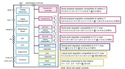
Designed to enable more compact electronic control units for automotive vision systems and other in-vehicle applications, STMicroelectronics’ new L5965 contains seven different regulators. These consist of two battery-compatible buck pre-regulators (one of which is a controller), two buck post-regulators with internal compensation, one boost that can be used to supply (e.g., a CAN bus), one LDO, and a 1% accurate reference voltage regulator for the microcontroller. All of the regulators, except for the BUCK 1 pre-regulator, have internal power switches.
With seven regulated outputs, a single L5965 can power an entire camera- or radar-based ADAS system, including the sensors, memory ICs, processor, and CAN interface circuitry.
The part works by leveraging direct operation from battery voltage with register-programmable output voltages and sequencing plus integrated functional-safety mechanisms. Being able to operate directly from the vehicle battery allows the devices to be used without a pre-regulator. Its register-programmable outputs also eliminate voltage-setting resistors, and the on-chip regulators can be used without external compensation circuitry.
This simplified block diagram reveals the key components of ST’s L5965 power-management chip.
While reducing both footprint and bill of materials (BOM), these savings in external components also increase system reliability and enhance accuracy by eliminating fluctuation due to environmental effects on external components.
All output voltages can be selected via OTP (One Time Programmable) memory cells that are able to be programmed before using the power-management IC. OTP cells are used for main device parameters and power up phase programming. Through the OTP, it’s also possible to decide the switching frequency of some regulator and the current limitation, as well as select the main buck and system power-on sequence. In addition, programming can be done at the customer’s production line.
Furthermore, an SPI interface can be used for diagnostic information (e.g., to communicate the status of the bucks in case of fault, over-temperature, or other events) and to program internal block parameters. With this bus, it’s possible to set overvoltage and undervoltage thresholds, enable the spread spectrum, select the soft start time, and perform other tasks. The maximum free run switching frequency of the bucks is 2.4 MHz, modifiable through external synchronization signals. The device can manage watchdog and reset signals.
According to STMicroelectronics, the integrated functional safety features are designed in compliance with ISO 26262 and enable systems to fulfill Automotive Safety Integrity Level (ASIL) requirements up to ASIL-D. The mechanisms include a failure status pin, voltage monitors, ground-loss comparators, analog and digital built-in self-test (BIST), and temperature monitors.
STMicroelectronics is ramping up production of the L5965. Samples are available now in a 7- × 7-mm QFN48 package that doesn’t require a heatsink.


