11 Myths About SMARC 2.0

This file type includes high-resolution graphics and schematics when applicable.

SMARC (Smart Mobility Architecture) 2.0, the new form-factor specification from the Standardization Group for Embedded Technologies (SGET), was launched in June 2016. Engineers may now wonder whether there’s a need to switch from other module form factors to SMARC 2.0. This article aims to dispel the myths that may be circulating around SMARC 2.0 and its position in the market.
1. SMARC 2.0 doesn’t offer as much performance as COM Express.
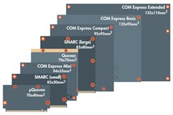
This is true when comparing SMARC 2.0 with COM Express Basic or COM Express Compact modules. It’s not true when compared with COM Express Mini modules, though. COM Express Basic modules are 125 x 95 mm and COM Express Compact measures 95 x 95 mm; consequently, these form factors are able to host processors with higher performance. When looking at the 84- x 55-mm COM Express Mini, the form factor delivers comparable performance to the 82- x 50-mm-sized SMARC 2.0.
2. SMARC has less interfaces then COM Express.
Like Myth 1, conditions apply here, too. The COM Express Type 6 and Type 7 specifications offer 440 pins on A/B and C/D connectors. COM Express Type 10 offers 220 pins on the single A/B connector. SMARC 2.0 has 314 pins; more interfaces than COM Express Mini. So, only those applications with interface requirements that exceed the capabilities of SMARC 2.0 need consider PICMG’s COM Express specification.
3. SMARC is a replacement for Qseven.
This is false. Qseven features 230 pins, which means it’s a better option for smaller, low-power designs requiring less interfaces. As a result, it can also represent a better cost alternative to the fully featured SMARC 2.0 modules. Furthermore, Qseven is well-established in the embedded market and has a broad range of supporters, ensuring that Qseven will remain the better design candidate for deeply embedded and cost-effective embedded-system designs.
4. SMARC 2.0 is only for x86.
This, too, is false. The specification has been designed to support all new, low-power processors that are planned in both the ARM and x86 families. SMARC 1.1 modules already provide a good balance between ARM and x86 options. This means that with SMARC, as with Qseven, there are no limits on the processor architecture. Both form factors enable the development of products with very low power dissipation.
5. SMARC 2.0 has no support for wireless interfaces.
This is wrong for two reasons. In general, it’s always possible to design a dedicated carrier board to provide any form of required wireless connectivity. But SMARC 2.0 offers a brand new additional option that aligns the module concept with wireless connectivity.
The SMARC 2.0 specification now provides a special area on the module itself that’s dedicated to the placement of the miniature RF connectors (short u.FL connectors) required for high-frequency signals. All SMARC 2.0 modules that need antenna connectors for wireless interfaces have these connectors in the same position, to ensure consistent interchangeability. For example, recently launched modules support WLAN and Bluetooth, in line with the M.2 1216 interface specification. This allows for a wide choice of radio protocols, which in turn creates highly flexible customization for end-user applications.
6. SMARC 2.0 has dropped the camera-interface support.
If referring to parallel camera interfaces, then this is true. But rather than dropping them, SMARC 2.0 replaced them with two serial MIPI CSIs (camera serial interfaces). While the first port supports two data channels, the second port supports twice the camera data rate, since it can operate with up to four data channels. Both camera interfaces can be implemented in accordance with either MIPI CSI 2.0 or the newer MIPI CSI 3.0 specification. In addition to a higher data rate, version 3.0 uses differential pairs to configure the connected cameras instead of an I2C bus.
7. The second Ethernet interface on SMARC 2.0 needs to be routed via PCIe.
This is false. SMARC 2.0 implements two native Gigabit Ethernet (GbE) ports, which is a particular advantage for Internet of Things (IoT) or Industry 4.0 applications. Without any special hardware effort, it’s now possible to realize two independent networks with fully separate logic and security aspects. And the two GbE ports also allow for the implementation of cable-saving line and even redundant ring topologies.
Both Ethernet ports further provide software-defined pins (SDPs) on the SMARC 2.0 connector. These Ethernet controller I/Os are configurable and can be used for hardware-based IEEE 1588 Precision Time Protocol (PTP) implementation. Such hardware-implemented PTPs can achieve nanosecond accuracy, whereas software-based solutions require microseconds. This way, developers can achieve the highest synchronicity between multiple local devices and realize powerful IoT gateways—also in combination with WLAN.
8. SMARC 2.0 uses expensive HDMI signaling.
Again, this is false, although it’s an option. SMARC 2.0 supports 2x24-bit LVDS/eDP/MIPI DSI as well as HDMI/DP++ and DP++. These two dual-mode DisplayPorts are very flexible. Systems that support DP++ for external displays can be controlled via DisplayPort, HDMI, and even VGA signals. The signals that are exchanged depend entirely on the cables used, some of which include active electronics for this purpose.
Another advantage is the fact that there are no license fees—in the case of HDMI, this can cost system manufacturers $10,000 annually. The latest version of DisplayPort, version 1.4 (released on March 1, 2016), supports screen resolutions up to 7680 x 4320 pixels.
The control of internal displays is also designed to be very flexible and forward-looking in SMARC 2.0. Low-voltage differential signaling (LVDS) is now the most common interface. But, thanks to the two 24-bit data channels, it’s also possible to drive high-resolution displays. Available along with the display signals is a complete set of support signals. As a result, the configuration data of the graphics can be transmitted via the I2C bus.
It’s further possible to control the power supply with two separate signals (VDD_EN). Backlight brightness can also be controlled separately for two panels via the Enable signals that turn on the backlight (BKLT_EN) and the pulse-width signal (BKLT_PWM).
9. The upgrade path from SMARC 1.1 is difficult.
To achieve the technological leap delivered between SMARC 1.1 and revision 2.0, 105 out of 314 pins—roughly a third of all signals—were changed. However, the specification ensures that using a new module in an older carrier board will not cause any destruction.
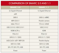
Whether it’s possible to achieve the exact level of functionality without any design effort depends entirely on the individual application. Thus, it requires a case-by-case examination. Vendors such as congatec provide free revision checks and advice on necessary redesigns of existing carrier boards as part of its individual integration support. The table above shows exactly what has been changed.
10. Carrier boards are the OEM’s secrets.
This is true when referring to dedicated, custom-built carrier-board designs. But, for many OEMs, there’s no need for custom-made carrier boards, or any benefit in designing everything from the scratch. Starter kits are available with fully featured carrier boards. In addition, many module vendors serve their OEM customers with sample PCB designs to help facilitate custom carrier-board layouts. Design guides from the SGET and module vendors complete the support. When working with module vendors that provide personalized integration support, use of this embedded technology is comprehensively simplified.
11. The first SMARC 2.0 modules will not be available until 2017.
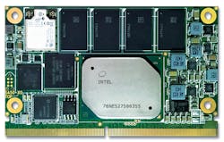
This isn’t true—they reached the embedded community last October, with the launch of the new Intel Atom, Celeron, and Pentium Processors (codename: Apollo Lake). These processors are a perfect match for low-power designs and small-form-factor systems. The new Intel Atom variants are even designed for extended temperature ranges from –40 to +85°C, which is a perfect match for many outdoor projects in smart cities, smart grids, and many other IoT and smart automation projects.

About the Author
Dan Demers
Director of Sales & Marketing – Americas, congatec
Dan Demers holds a B.B.S degree in International Business from Grand Valley State University, Grand Rapids, Michigan and an M.B.A. from Ashford University, Clinton, Iowa. Mr. Demers has over 22 years of experience in embedded computing, having worked with Fortune 500 companies in the industrial, medical, and communications markets.
Comment About the Article
To join the conversation, and become an exclusive member of Electronic Design, create an account today!

Leaders relevant to this article: