Use BLDC Fans To Create The Next Generation Of Thermal Management
We are living in a digital age, with a plethora of tablets, mobile phones, laptops, and practically any other digital device one can imagine. Each of these devices is sending data to and receiving data from a nebulous place called the cloud. The cloud itself is a network of switches, servers, and storage-area networks (SANs), which all generate massive amounts of heat.
This file type includes high resolution graphics and schematics when applicable.
Thermal management systems keep these systems cool so they can stay active and do their job. Typically, they comprise a dedicated IC such as an ADT7476, some diodes to measure temperature, and an array of multi-wire brushless dc (BLDC) fans to create enough airflow to keep the system stable. However, canned thermal management solutions limit system engineers from truly developing an optimal design for their application.
Recently, there has been a shift to developing more custom thermal management systems that allow engineers to adapt to evolving system needs as the development cycle advances. This saves time identifying parts and enables system engineers to create a less expensive yet more robust system. To accomplish this, two-wire, three-wire, and four-wire fans are being phased out alongside fixed-function thermal management devices in favor of two-phase and three-phase BLDC fans that are directly controlled by system-on-chip (SoC) devices that integrate the entire thermal management system.
Why Brushless Over Brushed DC Fans
The best way to start the discussion of why more designs should move to using two-phase and three-phase fans is to understand why BLDC fans (or rather motors) are used in the first place. It all started years ago with brushed dc motors. Brushed motors are among the easiest to control since they do not require any special circuitry or drive logic. All that is required is the motor itself along with an H-bridge for directional control.
But brushed DC motors are not ideal for fans for several reasons, particularly reliability (Fig. 1). For many applications, fans must be able to run continuously for years. Brushes wear out over time, though, and the fans have to be replaced. The failure rate increases even more as dust collects in the system, causing system downtime and recurring replacement costs.
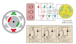
Due to the shortcomings of brushed dc motors, BLDC motors were developed (Fig. 2). They offer tremendous advantages, including greater torque, increased efficiency and reliability, and longer lifetimes from a lack of brush and commutator wear. They also eliminate sparking from commutators and reduce overall electromagnetic interference (EMI).
Additionally, there are no windings that need to be supported by the housing, so the motors can be cooled via conduction. The motors’ internals then can be completely enclosed and protected from dust and dirt, making them ideal for fans and perfect for spending years deployed in a data center. Yet these advantages come at a cost.
First, BLDC motors require additional electronics to properly control and commutate the motor, due to the lack of a commutator and brushes. Second, commutating the motor properly requires some type of position detection, which is typically achieved with Hall effect sensors, rotary encoders, or back electromotive force (BEMF) detection. Third, some type of microcontroller or microprocessor is required to use the position information and to perform the commutation.
Understanding Multi-Wire Fans
Current thermal management systems employ two-wire, three-wire, or four-wire fans, with different signals associated with the wires:
• Two-wire fan: power and ground wires
• Three-wire fan: power, ground, and a tachometer output
• Four-wire fan: power, ground, a tachometer output, and a pulse-width modulation (PWM) drive input
The tachometer output provides a square-wave output with a frequency that is proportional to the fan speed. The PWM input uses the pulse width of the input signal to adjust the power applied to the motor and, thus, the speed. The speed of two-wire and three-wire fans can still be controlled, though the process is a bit more involved. It needs to be adjusted by changing the dc voltage that is supplied to the fan itself, so a method to vary the voltage is required. The challenge is that with two-wire fans, there is no feedback in terms of a tachometer output, which is used to develop a closed-loop system.
Speed control in a thermal management system is important for several reasons. Running fans at a slower speed reduces the emitted noise and the power consumed. It also increases the overall reliability and lifetime of the motor itself. However, it is not uncommon to see two-wire fans in smaller sizes such as 40 mm. This is one of the first major advantages of moving to two-phase and three-phase fans, since you can provide speed control and feedback on fans that normally would not have them.
Controlling BLDC Fans
Controlling a fan module can be as simple as providing a voltage. But on current multi-wire BLDC fans, something has to handle commutation. If you open the fan housing, you would see a small circular printed-circuit board (PCB) that holds all the various electrical components required to commutate the motor and return a tachometer output.
When moving toward direct-drive BLDC motors, you essentially take the electronics of the motor out of the fan and move them onto the PCB that the rest of thermal management system is on. Doing so is much easier than you think. To migrate the control logic from the fan module and implement a motor control methodology in an embedded device, two primary functions need to be implemented: position detection and commutation.
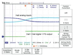
Of the three position detection methods mentioned earlier, Hall effect sensors are among the most common. Typically, the system is provided with Hall+ and Hall– signals that are fed into a comparator to produce a digital output. The microcontroller knows the proper time to commutate due to the toggling of the comparator output. Figure 3 shows the expected input and output in this implementation, which is captured from a two-phase motor.
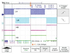
Once the position of the motor rotor is known, the next step is to drive the appropriate FETs at the appropriate time. Using a two-phase motor as an example, Figure 4 shows how each FET is driven for a specific period of time. One can see that commutating a two-phase motor is as simple as switching between driving the two high-side and low-side FETs. Implementing this logic can be as simple as an interrupt service routine (ISR) with a software state machine or more robust with a hardware-based state machine comprising digital logic.
Developing An Improved Fan Control Solution
When developing a custom thermal management solution, several design challenges need to be solved. The best way to go about solving these problems is to think about what design problems currently exist today and what can be done to solve them. Designers can tackle these challenges and develop a custom system using two-phase/three-phase BLDC fans that goes beyond what is currently available off the shelf.
Current monitoring has one of the greatest impacts on improving system performance. There are several ways to approach it, which can be broken up into three subcategories: current limiting, current measurement, and current protection.
The important thing to realize is that multi-wire fan solutions do not incorporate any current-limiting methods. Limiting the current into the system is important. Primarily, limiting the current on motor startup is essential to reducing the burden and design requirements of the system power supply. Additionally, inrush current from the fans on startup can cause the power supply to fail.
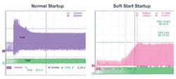
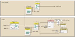
One potential way to implement current limiting is by using a hardware comparator with a programmable threshold that can provide a kill signal to the drive PWM. This, in essence, soft-starts the fans, reducing the inrush current and causing a gentle rise in overall power consumption (Fig. 5). This methodology also will control the current each fan draws throughout normal operation.
When controlling multiple fans with a single device, inrush current also can be limited by implementing a staggered startup methodology (turn on fan 1 and 2 first, then fan 3 and 4, and so on). By doing this, you allow time for the inrush from the first two fans to settle before the startup of the next two fans, rather than a massive inrush from turning all fans on at the same time.
One final method of limiting the current comes in the form of implementing a synchronization algorithm for the fan PWMs. Depending on the fan size, systems can have fans running at speeds up to 15,000 RPM and drawing 2 to 3 A. This forces power supply designers to ensure that the power supply being used can handle significant steady-state current draw when all fans are running at full speed. They also need to account for large instantaneous current spikes as the winding on all the different motors are switched on and off during the commutation cycles at different points.
One way around this is to synchronize the PWM drivers across all fans to enforce a phase delay between them so no two motor windings in the fans turn from off to on at the same point. By implementing this, the design requirements of the power supply can be relaxed due to the decrease in instantaneous current surges.
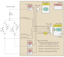
Current measurement goes beyond simply looking for the current to cross a specific threshold. It refers to the continuous measurement of the coil current through the use of an analog-to-digital converter (ADC). There are two benefits to having this information. First, ADC’s measurements can be sent across the SMBus to the backplane management controller (BMC) for general system monitoring. Second, a continuous measurement of the coil current can enable a method for predicting the failure of a fan.
Current protection, specifically over-current protection, is the last line of defense in a thermal management system when something goes catastrophically wrong. This is where the need to detect the current has exceeded the expected thresholds and the system must power down in an appropriate time frame to avoid damage. Similar to the current-limiting methodology, this is best accomplished with a comparator and programmable reference to provide the quick response time required.
Failure Detection And Prediction
Failure detection and prediction often are overlooked when developing a thermal management system. However, a couple of different implementations can be used to detect and predict the failure of a fan.
Using a real-time clock (RTC), the total time that the fan has been in operation can be tracked and stored continuously in non-volatile memory. Every time the system is power-cycled or reset, the previous time stored in the memory will be loaded and the lifetime will updated from that point. This allows for tracking how long the fan has been in service relative to the manufacturer’s specified mean time between failures (MTBF).
Another method for predicting fan failure is constant monitoring of the fan coil current, as mentioned earlier. As fans are deployed over an extended period of time, you can expect to see an increase in average current of the coils as the bearings in the fan wear. By monitoring for the average current, the systems service group can be alerted that the fan has crossed a threshold where a failure is imminent and the fan should be replaced.
Redundancy And Robustness
Redundancy is useful when compensating for a failure in the system. For example, in a thermal management system, multiple devices may be responsible for controlling fans in the system. Should one of those devices fail for whatever reason, it is important to become aware of the failure and adjust the thermal management profile to compensate for the lack of cooling. When developing a custom system, all of the devices can be tied together using status signals or a heartbeat. Should something go wrong, indicated by the heartbeat stopping, the other devices in the system can adjust themselves to handle the cooling burden until the failed module is replaced.
The robustness of the system can be increased by the addition of the ability to upgrade firmware via a bootloader. This is not your typical bootloader functionality where the system has to go offline to update the firmware image. Rather, dual-image bootloader functionality is deployed where one image can be updated while the other image is actively running and performing the job it is tasked to do.
One of the images is a golden image, which is an application image stored in flash that is protected from all write operations. Since this flash cannot be written to once deployed in the field, the factory has deemed the image “golden,” and it can always be used as a fallback image should something go wrong. Upgrades can be made to the writeable application image for updates to thermal profiles and features. Should something ever go wrong with the writeable image, such as flash corruption or a bug in the firmware, then the system can revert back to the known good (golden) image rather than bringing the system down.
Thermal Management Integration
At this point, many different improvements to fan control in thermal management systems have been identified. Implementing them all into a single embedded device minimizes bill of materials (BOM) costs. Many different SoC devices are on the market, each with a varying degree of analog and digital capabilities. The challenge is often finding a device with all the required peripherals.
Obviously some type of a soft core is needed. But other various digital logic, timers, and analog capabilities are required to implement PWM synchronization and various current protection, limiting, and measurement functionality.
Additionally, choosing the proper device can allow functionality beyond just fan control and temperature measurements. Functionality such as power management for monitoring and sequencing voltage rails in the system or I2C muxing all can be implemented into a single device, reducing the possible points of failure while reducing BOM cost.
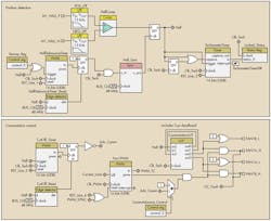
Today’s SoC devices, such as the PSoC family from Cypress Semiconductor, are highly integrated systems with a mix of analog and digital capabilities. Built-in analog functionality may include ADCs, comparators, and fixed-function voltage digital-to-analog converter (VDAC). Configurable digital resources can be programmed to implement timers, discreet logic, and custom Verilog circuits. A PSoC microcontroller can be configured using PSoC Creator to control a two-phase BLDC fan motor (Fig. 6). The fan control functionality can be implemented alongside temperature-sensing support as well (Fig. 7).
Conclusion
By adopting these techniques, you can increase the functionality and performance of your next thermal management system beyond what typical solutions employ. In addition, this all can be achieved at a lower cost point with improved reliability due to the reduced points of failure.
Engineers do not need to settle for a system that is good enough. Rather, they can develop an optimal approach where they have complete control over the system. Now is the time to look at current thermal management solutions and know there is a better way. Take back control of all aspects of the system and use BLDC fans to create the next generation of thermal management.
Robert Murphy is an application engineer at Cypress Semiconductor. He graduated from Purdue University with a bachelor’s degree in electrical engineering technology.
About the Author
Robert Murphy
Application Engineer
Robert Murphy is an application engineer at Cypress Semiconductor. He graduated from Purdue University with a bachelor’s degree in electrical engineering technology.


