Download Volume 3 of the Bob Pease eBook series.
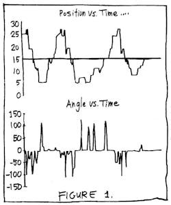
Several months ago, a reader showed me an application of Fuzzy Logic, which claimed to be excellent. The IEEE Circuits and Devices Magazine (March 1994, pp. 30-35) published an article by Dr. Hua Li and Dr. Yuandong Ji, showing how to balance a ball on a tilting beam. They showed how easy it was to use a little computer (well, actually, a 50-MHz '486-based PC) to get a ball to move to the center of a tilting beam. They claimed that Fuzzy Logic made a much quicker and smoother controller than a trained person. I present a copy of their results in Figure 1: The ball starts out, lurches along, crosses zero five times, and on the sixth try finally gets to stop at the center.
I asked the authors why it took six tries to stop, when any good controller would slow down and stop on the first pass. I asked them why the plot of the beam's tilt looked fishy. That's because sometimes when the beam tilted DOWN, the ball went DOWN. Other times when the beam tilted DOWN, the ball went UP. Sometimes the beam did not tilt at all, and the ball suddenly stopped. The Circuits and Devices Magazine published my questions in the Sept. 1994 issue, and also the authors' comments. Dr. Li's basic reply was to recommend that I ought to read a good book on Fuzzy Logic. And as for their results, Dr. Li could only respond, "I feel my professional practice and achievement respond louder an anything I can write".
After I researched this a little, and found almost no published information on a ball balanced on a beam, I felt challenged to make my own controller. After all, it isn't every day that I can replace a '486 with a simple $0.85 quad op amp. So when Bob Milne asked what I plan to do for a nice "Analog" column to run in the Special Analog issue in November, I knew this was the right topic.
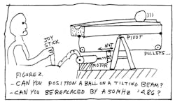
First I had to design a sensor. There's hardly anything simpler than V = I X R. I forced 0.50 A down a 3-ft. length of brass model-railroad rail (Zgauge) glued on top of a 1 in. x 1/4-in. X 3-ft. wooden beam (Fig. 2). As the metal ball rolled along on two rails, this voltage on the "hot" rail was transferred to the other rail-just like a wiper on a pot. The I X R drop was about 200 mV, so I fed that into a gain-of-plus-10 preamp to get 2 V full scale. (I mention this because Li and Ji, like most F.L. experts, do not like to mention their sensors.)
I bought several ball-bearings, 3/4-in., 7/8- in. and 1 3/32-in. diameter, at Performance Bearings on 3rd Street in San Francisco. I figured there might be some reason the larger balls would work better. Actually there was no difference. Professors Li and Ji did not disclose what they were using for a sensor, but they were apparently shining some kind of LIGHTS onto their ping-pong ball, and detecting the edge of the shadow. That seemed very awkward, as they appeared to have more than one light source. I figured my steel ball would make an excellent pot wiper. And I was right. Note, a ping-pong ball has more air-friction— it's easier to make it stop, but harder to get it going. A ball-bearing has very little friction, so it's a tough test to get it to stop.
To drive the beam and control its tilt, I used a surplus dc motor with a lead-screw. (I could have clamped a piece of threaded rod onto the shaft of any motor, but this was easy.) I drove this motor with an LM3876 power op-amp running on ±18 V to get good speed. I used dental-floss (less stretchy than nylon cord) and pulleys to couple the horizontal motion of the lead-screw to the ends of the beam. I mention this because Li and Ji, like most Fuzzy Logic experts, never talk about their power amplifier or output transducer.
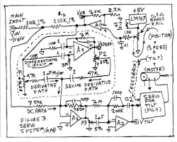
The dc path for the control amplifier was easy. I took the voltage from the sensor preamp (Al) and fed it back through R2 to the main control op amp, A2. But, if I just hooked it up this way, it would oscillate like CRAZY, because there are three integrators in the feedback path, not to mention the integrator action of A3 (Fig. 3). After all, the position of the ball is the integral of its velocity—and its velocity will be the integral of the beam's tilt! The dc gain will be INFIINITE, and any roll-off of the gain with frequency will surely be at 18 dB per octave. Very bad phase shifts! This loop is sure to oscillate if I don't intervene and put in some special tricks to make this loop stable.
I knew I could not use just a simple PID (Proportional, Integral, Derivative) controller of the type I discussed in a recent column (June 26, 1995), because when there are two or three integrators in the loop, a simple PID controller can't control the loop. But my plan does look like a PID with the addition of extra circuits (differentiators).
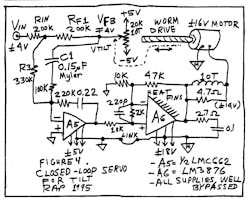
First, I put the motor inside a feedback loop, so the motor's lag would be effectively decreased to a negligible amount (Fig. 4). Then we set up a pot to sense the tilt of the beam so we could close the loop. And then we built the tilt-servo. It worked the first time, but I had to make a couple changes:
- I had to add a heat sink for the power amplifier-the poor little amplifier kept going into thermal shutdown because I forgot to provide one!
- I had to decrease one capacitor's value (C1, cut 1 uF to 0.15 uF) since it was causing a long tail in settling. (If I had put a pot in there, I could have just turned the knob.)
Then we added a joystick (just a pot with a lever) so we could control the beam's tilt manually. Making the ball move over from one spot to another spot is NOT a really easy loop to control by hand. It requires thought and planning. It's fun to try. And it's still possible to have it run smoother and faster than Li's Fuzzy Controller.
Then we built the main loop, with the dc path and a couple of differentiators added in (Fig. 3, again). These signals help us anticipate that the ball is approaching the right place, to help the controller slow it down and stop. It's just like the Differentiator effect in a PID loop, but we have a Derivative and a Second Derivative. You might call this a PID2 Controller.
We fired it up and it worked pretty well the first time, with most of the pots set at maximum damping. But it didn't damp out too well until I fixed two more items:
- I had to cut down some friction in the pulleys.
- One amplifier was wired wrong in the differentiator.
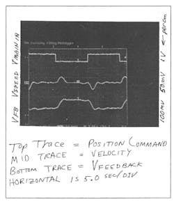
After that, it ran pretty well. The ball moves smoothly and only overshoots a few percent. It rarely lurches or jitters. I can use it to position the ball at any point on the beam. As shown in the scope photo (Fig. 5), the voltage that represents the ball position settles smoothly—just as the ball does.
I still don't know why my scheme is so slow; I want to figure out how to make it faster. There are several ideas I'd like to try out, and I've had several suggestions on making it servo and settle much faster. Maybe the integrator in the main servo loop is adding too much dc gain. I may be able to decrease friction with a dither, or a preload.
When I do get this working really well, I'll send a videotape to Dr. Li and Dr. Ji - just to show them how a beam balancer can work well. They claimed they got their best results because they didn't use any models. Mine runs well because I was able to use simple models: a rolling ball is a double integrator. They claimed their Fuzzy Logic was able to triumph over the nonlinearities of a tilted beam. Well, the approximation that sine of tilt angle = tilt is only nonlinear by a few percent. They still can't servo the ball to any place on the beam as fast as my PID2 controller.
If I get some time, I may be able to try out a deterministic solution: Bang the motor ON for a while, then when the ball has moved about half way, bang the motor to tilt the beam the other way. When the ball is nearly at its goal, then I'll servo the beam to be flat. This will require a bunch of tricky circuits, but if you're really in a hurry, this is surely the right way to do it.
P.S. Thanks for Jay Friedman's and Kevin Thompson's help.
PPS. In case the position sensor got flaky, I was prepared to buy a tube of carbon-loaded lubricant that's made by Planned Products of Santa Cruz. But we never had any trouble with that, so there was no need to buy that stuff. It's a little pricey, about $13 at Fry's, but it's nice to know it's there.
Comments, invited / RAP Robert A. Pease / Engineer
Originally published in Electronic Design, November 20, 1995
RAP's 1997 comments: My BOBB keeps on plugging. When I published this in '95, 1 had gotten the settling time down to 8 seconds. I added an R-C network from -Vin to the first summing point, and it didn't help. I added it again later, and it worked just fine, and helped me get the settling time down to 4 seconds, and 3.2 on a good day. How am I going to get it down to less than 2 seconds? More on this, later. I have seen a couple recent technical reports on BOBB using Fuzzy Logic. They are not bad at all. They seem rational. They are not hyped. And, surprisingly, they make no reference to the seminal Ji/Li article. More on this later.
Here I'll list three References from the magazine: IEEE Transactions on Fuzzy Systems. (Isn't it funny that dozens of F.L. enthusiasts gather there to say good things about F.L., and I'm the only protection you have from them?)
- "Designing Fuzzy Controllers from a Variable Structures Standpoint," J. Glower and J. Munighan, North Dakota State University, Fargo, N. Dak. pp. 138-144, Feb. 1997. They simulated a response of about 4 seconds, but had not built a model at the time of publication. Honest, realistic work. I'll add more comments later. They agree that adding P plus D terms before they are sent into the F.L. controller can improve and simplify the system, as I proposed above in my PID column.
- "How to Design a Discrete Supervisory Controller for Real-Time Fuzzy Control Systems," N. Muskinja et al., University of Maribor, Slovenia, May 1997, pages 161- 166. They show some curves with some not-entirely linear results, with settling in the range 4 to 8 seconds. They don't explain a lot about their analog-digital interface. But they use pulleys like I do.
- "Adaptive Fuzzy Control: Experimental and Comparative Analyses." R. Ordonez et al., Ohio State University, May 1997, pp. 167-188. They show comparisons between computer simulations and the systems they BUILT. Very honest guys. They actually wrote about their sensors and their interfaces. Very honest. They got results in the 4 to 6 second range. More on this, later.-rap
