Protect RS-485 Transceivers from Electrical Surges—and Maintain Signal Integrity
Download this article in PDF format.
The RS-485 is a popular serial communications standard that’s widely used in industry. It’s flexible, with the ability to achieve high data rates on long bus cables. The standard is relatively easy to implement, too, using available IC transceivers. However, one serious limitation is its vulnerability to electrical surges generated by nearby equipment. This problem has now been solved thanks to integrated protection circuitry, making the RS-485 almost “bulletproof.”
Sponsored Resources:
- Integrated protection for the most severe surges on the RS-485 communication lines
- Can your RS-485 communications survive the great outdoors?
- Signal integrity vs. transmission rate and cable length for RS-485 transceivers
Review of RS-485
RS-485 is a national and international standard of the American National Standards Institute (ANSI) and the Electronics Industry Alliance/Telecommunications Industry Association, and is designated EIA/TIA-485-A. It’s a wired communications differential bus made up of unshielded twisted-pair cable that greatly reduces the noise pickup. Figure 1 shows the arrangement.
1. The RS-485 bus forms a very versatile network for wide range of applications. Note that the bus must be terminated in its characteristic impedance of 120 Ω (RT) at both ends of the bus.
Transceivers made up of a receiver (R) and a transmitter (T) or driver (D) connect to the bus. Each transceiver is a communications node that may initiate or receive a message. Communications is half duplex. All transceivers receive a transmission at the same time. Though the standard indicates that up to 32 transceivers may be connected to the bus, special IC designs have been implemented to allow up to 256 nodes.
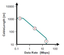
The maximum length of the bus according to RS-485 is 1200 meters or about 4000 feet. The standard can accommodate a wide range of data rates from a few kilobits per second to a maximum of 10 Mb/s. The upper data rate depends on the bus length and the number of transceivers connected.
Figure 2 shows the general relationship between the bus length and the maximum data rate. Point 1 is the maximum rate, while point 3 is the maximum bus length. The standard states that the approximate maximum rate at 4000 feet is 100 kb/s. The data rate at 40 feet can be up to 10 Mb/s. However, experimentation and wide usage have proven that even longer range and higher data speeds are possible. Rates up to 50 Mb/s have been observed with the right transceivers.
2. The relationship between bus length and data rate of RS-485 transceivers.
The Achilles Heel of RS-485
The major limitation of this standard is its vulnerability to electromagnetic interference (EMI). Because of its usual long cable and harsh operating environment, it’s subjected to all sorts of electrical surges depending on the location. Some RS-485 networks are used outdoors and subject to the biggest surge of all—a lightning strike. Others are deployed in industrial settings where motors, relays, and other inductive devices that regularly generate short-duration, but high-voltage, pulses are picked up on the bus. Being differential, the bus rejects a great deal of other noise, but it’s still susceptible to surges from surrounding equipment.
A standard for electrical surges has been established to help measure and quantify the potential danger. The International Electrotechnical Commission (IEC) developed the IEC 61000-4-5 standard that defines tests to determine the amount of protection needed by an IC to survive various types and levels of surges. Some of these tests include the long-duration 0.5-kV test, a 1-kV test, a 2-kV test, the 4-kV electrical fast transient (EFT) test, and the 10-kV electrostatic-discharge (ESD) test. Most products for outdoor service generally have to meet the 1- or 2-kV tests.
Implementing Surge Protection
The RS-485 transceivers making up the network are low-voltage silicon CMOS devices. These ICs incorporate some protection, but it’s just not enough for most use cases. These transceivers most definitely need more robust protection from their noisy environment.
In the past, such protection has been provided by a mix of external components such as metal-oxide varistors (MOVs), transient-voltage-suppression (TVS) diodes, and gas discharge tubes. One or more of these external devices are used in some validated combination to meet the standard. The protection devices end up taking much more PC board space than the transceiver IC itself and add extra cost. This limitation has now been overcome by the availability of RS-485 IC transceivers that integrate adequate protection.
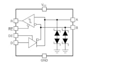
Texas Instruments offers IC transceivers that solve this problem—the THVD1419 and THVD1429. Both are TIA/EIA-485A standard compliant. The THVD1419 has maximum data rate of 250 kb/s, while the THVD1429 can achieve a data rate of up to 20 Mb/s. Integrated protection for the most severe surges on RS-485 communication lines is achieved by integrating TVS diodes on the bus lines (Fig. 3). No external protection devices are needed.
3. The THVD1419/1429 transceivers’ block diagram shows TVS protection diodes on the bus.
The bus protection specifications met by these transceivers include:
- ±16-kV HBM ESD
- ±8-kV IEC 61000-4-2 Contact Discharge
- ±30-kV IEC 61000-4-2 Air-Gap Discharge
- ±4-kV IEC 61000-4-4 Electrical Fast Transient
- ±2.- kV IEC 61000-4-5 1.2/50-µs Surge
Signal integrity versus transmission rate and cable length for RS-485 transceivers is discussed at length in this PDF document. It provides a review lab data for TI THVD1450 and THVD1429 RS-485 transceivers operating over a range of different cable lengths and data rates.
These transceivers operate from 3.3- to 5-V supply. Operational temperature range is −40 to 125°C. They come in 4.9- × 3.91-mm 8-pin SOIC packages.
Sponsored Resources:
About the Author

Lou Frenzel
Technical Contributing Editor
Lou Frenzel is a Contributing Technology Editor for Electronic Design Magazine where he writes articles and the blog Communique and other online material on the wireless, networking, and communications sectors. Lou interviews executives and engineers, attends conferences, and researches multiple areas. Lou has been writing in some capacity for ED since 2000.
Lou has 25+ years experience in the electronics industry as an engineer and manager. He has held VP level positions with Heathkit, McGraw Hill, and has 9 years of college teaching experience. Lou holds a bachelor’s degree from the University of Houston and a master’s degree from the University of Maryland. He is author of 28 books on computer and electronic subjects and lives in Bulverde, TX with his wife Joan. His website is www.loufrenzel.com.


