Protect, Recover, Repeat: Inside a Smart Automotive eFuse
What you'll learn:
- How automotive eFuses prevent a minor fault from becoming a major failure.
- How these circuits react and recover from short-to-ground and other short conditions.
- The importance of current sensing to engineer more robust circuit protection.
- The cost differential between a discrete and fully integrated eFuse.

In the first part of this series, we explored how an electronic fuse (eFuse) assembled out of power switches and high-speed comparators can protect against common short conditions. In this second part, we examine what happens after the occurrence of a fault. We dive into the recovery dynamics of the design after a short-to-ground condition and how to add diagnostic capabilities to it. In addition, test results are presented that show how this approach to automotive circuit protection performs with actual hardware.
Forcing a Reset: How eFuses Recover from Short Circuits
With the protection circuit leveraging a FET and comparator, a short-to-ground scenario can cause a latch-up condition. If the output shorts to ground, the second FET in the circuit (Q2) will turn off, and the comparator will “hold” the FET off.
Even after removing the short, the comparator will continue to hold the FET off because there’s no way for the VOUT node to have a higher voltage than the negative terminal of the comparator. This latches the circuit and prevents power conduction to the adjacent module (for reference, see Figure 8 in the first article in the series).
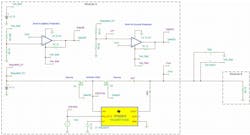
Simulating the circuit reveals the latch-up condition (Fig. 1). A time-control switch replaces the switch between VOUT and ground. This time-control switch will connect VOUT to ground at 2 ms and then disconnect VOUT from ground at 4 ms. The waveform clearly shows the switch connection to ground at 2 ms, forcing VOUT to ground. When the switch opens at 4 ms, however, the output doesn’t return to 5 V because the comparator is still holding Q2 off.

Placing a load switch in parallel to Q2 forces a voltage higher than the negative terminal onto the positive terminal (Fig. 2). A general-purpose IO (GPIO) in a microcontroller (MCU) or system-on-chip (SoC) resets the circuit by enabling the load switch, placing 5 V on VOUT (the positive terminal) and thus releasing the gate back to 12 V.
One important design aspect of the circuit is that the input of the load switch must connect to the common drain between the back-to-back FETs. This ensures that the circuit will still protect the system from short-to-battery conditions, since the load switch only has a single FET with the body diode in the same direction as that of Q2. Furthermore, it’s important to ensure that the load switch can handle battery-level voltages seen at VOUT.
For this example, it’s recommended to confirm that the load switch is rated higher than the maximum battery voltage of 16 V. The TPS22810-Q1 from Texas Instruments is a good fit as the reset load switch in this implementation.
No other loads should connect to the common drain between the back-to-back FETs. That’s because during a short-to-battery condition, the body diode of the load switch will be forward-biased, and too much current could damage the device. If the power path on VIN of the TPS22810-Q1 completes any other load (such as a fault event on VIN), the device will fail, since the body diode will not be able to handle the flow of reverse current.
>>Download the PDF of this article, and check out Part 1 of this series


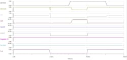
After 2 ms, the short-to-ground condition occurs, pulling VOUT down to ground (Fig. 3). At 3 ms, the load switch is enabled. At 4 ms, the short condition is removed as the time-controlled switch SW1 opens up. The VOUT returns immediately back to 5 V, and the gate of Q2 returns to 12 V. After 5 ms, the load switch turns off, and the circuit continues operating normally.
Using Real-Time Current Sensing to Prevent Damage During Reset
One drawback of this implementation is that the load switch is susceptible to conducting high current levels if the short-to-ground condition is still present when the load switch turns on, illustrated by the AM2 waveform. At 3 ms, a short-to-ground path runs through the body diode of FET Q1 and through the load switch. Adding diagnostics to the circuit (to determine output current levels) and quickly turning the load switch back off (if the short to ground is still present) will combat this scenario.
Incorporating a current-sense amplifier can help you understand the state of the module being connected and achieve diagnostics. In the initial example, you may want to know whether the antenna is connected, in an active state, or in some sort of shorted or open condition. The INA180A2-Q1 current-sense amp, combined with a 200-mΩ current-sense resistor, can detect these conditions.
These current draw numbers illustrate which system specifications determine the state of the antenna:
- Output current < 10 mA: potential antenna disconnection (open) or short-to-battery condition
- 10 mA < output current < 25 mA: antenna connected, inactive
- 25 mA < output current < 400 mA: antenna connected, active
- Output current > 400 mA: potential short-to-ground condition
The combination of the INA180A2-Q1 and the current-sense resistor results in these output voltages, which can be readily converted with the integrated analog-to-digital converter (ADC) within an MCU:
- Output current < 10 mA (potential antenna disconnection [open] or short-to-battery condition): INA180A2-Q1 output = 20 mV to 100 mV
- 10 mA < output current < 25 mA: INA180A2-Q1 output = 100 mV to 250 mV
- 25 mA < output current < 400 mA: INA180A2-Q1 output = 250 mV to 4 V
- Output current > 400 mA (potential short-to-ground condition): INA180A2-Q1 output = 4 V to 5 V
The current (represented as a digitized voltage) provides diagnostic information to control the turn-on time of the TPS22810-Q1 during the short-to-ground condition reset state. The INA180A2-Q1 has a high bandwidth of 210 kHz, which will react quickly upon the detection of a short-to-ground condition at the output.
If a short-to-ground condition is present, the system will want to turn off the TPS22810-Q1 as quickly as possible to keep the device from heating up. The turnoff time will largely depend on the MCU ADC read time and the GPIO assertion time.
In addition, the system should only turn the TPS22810-Q1 on for a diagnostic check intermittently, so that the load switch can cool off between tests if a short-to-ground event persists.
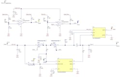
The complete solution is outlined in Figure 4.
Putting the Protection Circuit to the Test
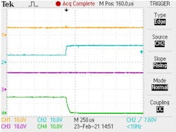
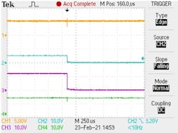
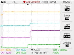
Figures 5, 6, and 7 show results of testing the design with actual hardware.
Balancing Performance, Flexibility, and Cost in Automotive eFuses
Verifying the voltage across the FETs and current-sense resistor is vital to ensuring that everything works in this application. This example uses Diodes Inc.’s DMN2050LFDB automotive-grade FET. Each FET has approximately 45 mΩ of RDS(on). Since the power devices are placed back-to-back, the total RDS(on) will double to approximately 100 mΩ. Adding a 200-mΩ current-sense resistor in series results in a total of 300 mΩ between the power supply and VOUT.
Given a maximum normal operating current of 400 mA, you can use Ohm’s Law to calculate the voltage drop against the combined series-connected components as V = I × R = 400 mA × 300 mΩ = 120 mV. Subtracting the 120 mV from the 5-V supply results in an output voltage of 4.88 V, which is well within the 4.5-V tolerance limit of module B. Notably, this also leaves room for any additional voltage drop from the resistive cable losses.
Perhaps the most significant facet of the design is its minimal cost. There are more tightly integrated solutions that can accomplish virtually the same result in a smaller space. For example, the TI’s TPS25940-Q1 is a fully integrated eFuse available in a 3- × 4-mm package, which is much smaller than the space required for all of the discrete components. However, comparing the 1,000-unit pricing of the main components in each solution shows the cost savings of the discrete solution (see table).
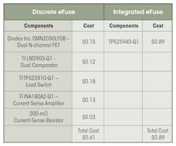
Engineering often comes down to managing tradeoffs. So, although the discrete eFuse isn’t the smallest solution available, it does offer a cost-aggressive approach with plenty of opportunities to optimize your end goal.
>>Download the PDF of this article, and check out Part 1 of this series
About the Author
Jared Becker
Technical Sales Engineer, Texas Instruments
Jared Becker is a technical sales engineer for Texas Instruments. He has a BSEE degree from Arizona State University and has been with TI for over 10 years.
Comment About the Article
To join the conversation, and become an exclusive member of Electronic Design, create an account today!

Leaders relevant to this article: