Defuse the Dangers of Automotive Short Conditions with eFuses

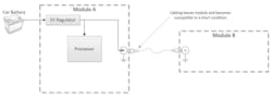
In automotive systems, the integrity of every electrical connection is critical. But the cables connecting electronic modules are constantly at risk from two common failure modes: short-to-ground and short-to-battery.
A short-to-ground occurs when shorting two wires together or shorting a wire to the metal frame. It can be caused by the degradation of insulation in cables, damaged connectors, or even by misplacing a screw into the wiring harness during manufacturing. Short-to-battery conditions will emerge when signals in the electrical system short to the battery voltage (VBAT).
Both types of faults can expose electronic modules, components, or circuits to voltages and currents beyond their specified ratings, often with costly or dangerous consequences (Fig. 1).
Many ICs implemented in automotive applications feature power switches with current limiting and fault outputs to detect and safely handle these shorting conditions. When a short-to-ground or short-to-battery event occurs, these devices send a fault signal — typically routed to an output pin — alerting the system to take protective action. In response to a detected fault, the device may automatically shut down or limit the current to prevent damage to itself and other components in the system.
However, not all components and circuits in the system have the same internal diagnostic and protection features. And even when protections are present, they may not defend against every type of automotive short.
>>Download the PDF of this article, and check out Part 2 of this series


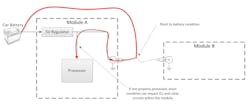
Consider a DC-DC converter that applies power to both internal components on the PCB and cabling connected to a module (Fig. 2). While the power supply may protect against short-to-ground events, components on the PCB can still be susceptible to a short-to-battery condition, which could easily cause damage. Ultimately, protecting the processor and everything else on the PCB requires careful circuit-level design.
While fully integrated electronic fuses (eFuses) are becoming more widely applied in data centers and the like, this article shows how a series of power FETs can be used to design a discrete e-fuse that provides short-to-ground and short-to-battery protection.
When Diodes Protect Automotive Power Systems — And When They Don’t
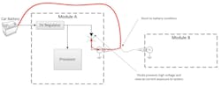
A series-connected diode is a common protection method to guard against a short-to-battery condition. When cabling shorts to a voltage higher than the anode of the diode, the diode will become reversed-biased, ensuring that the system voltage on the anode side is fully protected from exposure to the high voltage. This also prevents any reverse current (Fig. 3).
However, series-connected diodes come with several drawbacks, most notably the large forward-voltage drop when in forward conduction.
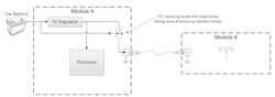
Consider a common example where one module is providing power to an antenna on another (Fig. 4). Module B requires 5 V (±10% tolerance) to power the antenna, which is generated from a 5-V regulator on module A. In this case, a standard diode forward voltage of 700 mV would limit the voltage at module B to 4.3 V, which is below the antenna module requirement of 4.5 V (5 V minus 10%).
A potential solution involves using a Schottky diode with a lower forward voltage drop of about 200 to 300 mV. But Schottky diodes are generally more expensive than standard diodes, and they only protect against the unique short condition where the cathode is at a higher voltage than the anode. Neither a silicon diode nor a Schottky diode will protect the system from a short-to-ground condition.
On top of that, the 200- to 300-mV forward-voltage drop of the Schottky diode hinders the addition of diagnostic features to the circuit.
Using FETs to Address Short-to-Battery Conditions
An N-channel field-effect transistor (FET) can be used to implement short-to-battery protection without the large voltage drop associated with a series-connected diode.
This implementation ensures that the body diode of the FET is aligned in the same direction as a series-connected diode. Driving the gate of the N-channel FET with the vehicle battery ensures enough voltage to fully enhance the FET. So, as long as the source voltage is below the vehicle battery voltage by at least the threshold voltage rating of the N-channel FET, the N-channel FET will have minimal RDS(on), and thus minimal voltage drop.
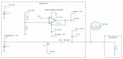
A short condition requires some additional circuitry to turn the FET off quickly. A simple comparator can rapidly force the gate voltage low when applying a voltage to the output that’s greater than the expected 5 V.
A wide-VIN comparator such as the TL331B-Q1 from Texas Instruments plays a critical role in this situation, as it’s possible to expose the negative terminal to high voltages during a short-to-battery condition. You would design the comparator circuit by connecting the module output voltage after the FET (VOUT) to the negative terminal of the TL331B-Q1 (Fig. 5). The goal is to ensure that the comparator output drives the gate of the FET lower when the voltage at VOUT exceeds the target output voltage by a preset amount.
Assuming the earlier example, 5 V ±10% at VOUT, it makes sense to set the reference to above 5.5 V (5 V plus 10%) and create a reference voltage with a simple resistor divider from the battery, which is nominally above 5.5 V.
Many automotive circuits are required to operate properly between a voltage of 9 and 16 V because the battery voltage can fluctuate in real time. In this case, I’ll set the reference voltage to 8 V with a voltage divider of 500 Ω and 1 kΩ from the 12-V battery.
Examining the voltage extremes, a minimum battery voltage of 9 V results in a reference voltage of 6 V, which is still above the 5.5-V threshold. If the battery voltage is as high as 16 V, the reference voltage will be approximately 10.7 V, which is still a reasonable reference voltage to detect a short-to-battery condition.
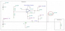
When activated, the comparator forces the FET off, while the body diode of the FET ensures that there’s no high-voltage exposure on the source side of the FET and the reverse current is minimal. When shorting the output to VBAT (12 V in this case), the regulated 5-V rail stays at 5 V (Fig. 6). A single FET, however, doesn’t solve the problem of a short-to-ground condition, since the body diode will conduct in that scenario.
Tackling the Challenge of a Short-to-Ground Scenario
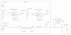
A short-to-ground condition requires adding a second FET to the system with the body diode facing in the opposite direction (Fig. 7), which stops excessive current flow from the power supply during fault conditions. Similar to the first FET, during normal operation, the gate of the N-channel FET will be driven by the higher-voltage battery (12 V) to fully enhance the FET.
A short-to-ground condition requires additional circuitry to turn the FET off quickly — exactly like a short-to-battery condition. Once again, a simple comparator can rapidly force the gate voltage low when applying a voltage to the output that’s lower than the expected 5 V.
In this situation, a second wide-VIN comparator (the TL331B-Q1) is required (Figs. 7 and 8). The comparator circuit comes together by connecting the module output voltage after the FET (VOUT) to the positive terminal of the TL331B-Q1.
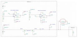
It’s necessary to create a second reference voltage to ensure that the comparator output drives the gate of the FET low when the voltage at VOUT is below the target voltage by a predetermined amount. Given the example with 5 V ±10% at VOUT, set the reference below 4.5 V (5 V minus 10%). Create a reference voltage of 4 V using a voltage divider of 1 kΩ and 4 kΩ connected to the 5-V regulated rail.
Since this design leverages two comparators, the LM2903B-Q1, also from TI, is used to integrate them into a single parametric-equivalent device. The back-to-back FETs, in combination with the dual comparators, create the foundation for a discrete eFuse.
The second installment of this series takes a detailed look at eFuse recovery from a short-to-ground condition, additional circuit diagnostics, and testing of the circuit.
>>Download the PDF of this article, and check out Part 2 of this series
About the Author
Jared Becker
Technical Sales Engineer, Texas Instruments
Jared Becker is a technical sales engineer for Texas Instruments. He has a BSEE degree from Arizona State University and has been with TI for over 10 years.
Comment About the Article
To join the conversation, and become an exclusive member of Electronic Design, create an account today!

Leaders relevant to this article: