Electronic Fuses: The Future of Power Protection in Data Centers?

This article is part of an Electronic Design special report.

What you'll learn:
- The MOSFET: The Power Control Switch for Hot Swapping
- Hot-Swap Controller: Protection from the Power MOSFET to the Load
- Inside the First 48-V Electronic Fuse for Data Centers
- The Future of Hot Swapping on High-Voltage DC Power Rails
As graphics processing units (GPUs) and other artificial-intelligence (AI) chips push the power limits of data centers, it’s becoming vital to prevent the current racing into them from overloading the system and causing costly disruptions.
When a server or other electronic module in the data center fails, it must be “hot swapped” to keep downtime to a minimum. In this case, hot swapping means removing the faulty hardware and replacing it while the other servers in the rack keep running.
However, that process can introduce a huge amount of inrush current when plugging the server into the rack. The sudden increase in current can stress out the processors, accelerators, and power circuits in the server, potentially leading to component degradation or even failures.
To power up everything safely, a power MOSFET is typically placed in the server with a current sensor and a digital controller. Together, they serve as a circuit breaker for the system, regulating the inrush current when powering up and then keeping track of the supply current during regular operation to prevent short circuits or any other faults. But Robert Taylor, GM of industrial power design at Texas Instruments, said power designers and systems engineers are struggling to scale up these hot-swap solutions within the space constraints of AI servers.
TI and others are rolling out electronic fuses, or eFuses, to safely handle the huge amounts of power used by AI. They integrate the power device, current sensing, and digital control in a single chip that delivers more intelligent power-path protection. Taylor said its latest electronic fuse—the TPS1685—can detect faults more accurately and intelligently and respond to them faster than other hot-swap solutions. It also includes a black box for fault logging.
While eFuses are becoming more widely used for hot swapping, TI said the TPS1685 is the first to handle the 48-V DC bus, which is replacing the traditional 12 V architecture as the industry standard for in-the-rack power distribution.
According to Taylor, several of these 20-A eFuses can be stacked together to scale with the rising power demands of AI, which are pushing power requirements to more than 100 kW per rack. “Each one of these chips is able to power about one kilowatt,” he said. “But there is no limit to the number of these that you can put in parallel. The power FETs are integrated, and we control everything between them, so we can make sure that they share current. They are thermally sharing between the different packages as well.”
The MOSFET: The Power Control Switch for Hot Swapping
In a 48-V architecture, the power-supply units (PSUs) in the rack convert the AC used to distribute power around the data center into the 48 V DC used by the servers themselves. The DC power is distributed to the servers through the 48-V backplane that runs down the back of the cabinet. If a server malfunctions, the load is shared by the others to keep everything running long enough for a replacement to be hot swapped into the system.
The capacitors on the circuit board serve to smooth out voltage ripples and remove noise, supplying stable power to the processors, memory, and other building blocks of AI servers. When the server is plugged into the rack, these capacitors require as much current as possible to charge up the processor, accelerator, and other loads, creating a large amount of inrush current for a short time. If the current isn’t limited, it can overload the connectors or the other components in the server or cause sudden fluctuations in voltage that could reset the servers around it.
The latest high-performance AI chips are burning through more than 1,000 W of power to run AI training and inferencing, which is increasing the amount of current required by AI servers. To power up everything safely during hot swapping, a MOSFET is placed close to the server’s power connectors to enable and disable the distribution of power to the processor and other loads. The gate voltage of the power device determines the current passing through to them.
When the power MOSFET is turned off—when the gate voltage (VGS) is under the threshold voltage (VTH)—it prevents current flow into the system, blocking inrush current while the server is hot swapped into the system.
But when the power MOSFET is turned on—when the VGS is above the VTH—it enables a constant amount of current to proceed into the system. In this situation, the MOSFET enters the saturation region, where the VGS is the primary factor controlling the drain current. As the VGS increases, the power MOSFET pushes more current into the input capacitor in the system. As the current increases, the voltage between the drain and source (VDS) of the FET falls, placing the power device in the ohmic region, where the current depends on the resistance (RDS(on)) between the drain and source.
These power FETs require a wide safe operating area (SOA) to prevent the current racing into the system during hot swapping from damaging the power device (or the components around it) or causing it to overheat. To handle larger amounts of current, several of these power FETs are usually placed in parallel. By spreading out the current over several different power FETs, the heat inside them can also be reduced, said TI. That’s also important because high temperatures can increase the overall resistance inside the FET, restricting current.
Hot-Swap Controller: Protection from the Power MOSFET to the Load
While a shunt or other current sensor checks on the current flowing into the server and the MOSFET connects or disconnects power to the server, the hot-swap controller controls the MOSFET and keeps it within the SOA.
The digital controller regulates the gate voltage of the power MOSFET to control the amount of current racing into the system during hot swapping. It’s also used to check out the current, voltage, and temperature in the power FET at all other times to prevent short circuits or other faults. At its heart is a programmable timer, which limits how long the power FET remains in regulation during faults. If the fault condition lasts too long, the power FET shuts down. The power FET must have a large SOA to limit power losses as the timer runs down.
The primary role of the hot-swap controller is to set the system’s current limit—it integrates short-circuit and overcurrent protection (OCP) in the event the current runs over the threshold. In many cases, these chips also offer undervoltage lockout (UVLO)—which prevents damage to the power FET that can occur due to fluctuations in the gate voltage—and overvoltage protection (OVP)—which stamps out voltage spikes or problems with the supply voltage. Furthermore, hot-swap controllers often have thermal protection to prevent the FETs from overheating.
Taylor said TI and other semiconductor companies are rolling out hot-swap controllers that integrate gate driving and current-sense amplifiers to more efficiently handle the huge currents used by high-performance AI chips. However, he said they still require separate power FETs to cut power to the load during fault conditions, while shunt resistors or other current sensors are placed with comparators on the same power rail as the FET.
But these solutions are getting more complicated at a time when power boards in data centers are becoming more densely populated. “If you look at the evolution of hot-swap protection, we used to use a lot of separate components—maybe a current-sense amplifier, a comparator, a current sensor, a power FET—and all these different components take up a lot of space on the PCB, and they have made it more challenging for engineers to place all the components” in a way that maximizes safety and minimizes power losses, said Taylor.
He added that given the growing power demands of AI chips, it’s also more challenging to detect fault conditions and shut them down fast before they can damage the processor, accelerator, or components around them.
Inside the First 48-V Electronic Fuse for Data Centers
The future of hot swapping, said Taylor, is the eFuse. By integrating the power switch, digital control, current sensing, gate driving, and all of the other smarts for hot swapping in a single chip, the TPS1685 reduces complexity and saves space in the system.
“We’ve integrated all of these into a single package, so where customers are currently using a hot-swap controller and power FETs today, we can take all of those parts and put them into the same device,” explained Taylor. “We can not only monitor the power FET and make sure it’s always operating in a safe area, but we can also do predictive maintenance on the FET and detect when there are issues with that part of the device.”
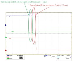
At the heart of the new eFuse is a “blanking” timer. It prevents false tripping by enabling the system to distinguish between peak load currents and actual overcurrent faults.
Today, AI server chips have distinct power characteristics, often requiring sudden and large inrushes of current to handle computationally heavy workloads, which can unintentionally cause the circuit breaker to trip. Taylor said the user-programmable timer enables these load transients to travel through the eFuse, preventing them from shutting down the system.
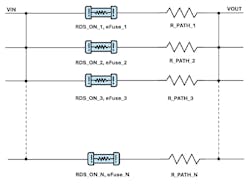
TI noted that the TPS1685 can also be stacked together to handle the rising power demands of AI. Placing discrete power FETs in parallel is challenging due to slight differences in the RDS(on) of the devices and resistances in the PCB traces between them, said Taylor. If any one of the power FETs is forced to handle more current than the others during hot swapping, it can shut everything down even if the system’s total current is under the trip threshold.
To mitigate that, power electronics and systems engineers add margins to make sure that none of the power FETs are taking on more current—and thus, taking on more heat—than the others during hot swapping. The challenge with adding these margins is the complexity of it. “One of the bigger problems with paralleling these devices is having to make sure the mismatches between these different parts are taken into account,” said Taylor.
TI solves the problem by actively sharing the current between the power devices. One of the eFuses is promoted to the role of the primary controller for the system, overseeing the current of the entire system. By measuring the total current instead of monitoring for issues with any one eFuse, the system can assess the situation more accurately during the hot swapping and cut power to the load only when required.
When the controller notices that one of the eFuses is handling significantly more current than the others, it redistributes the current by dynamically increasing its RDS(on). TI said this dynamic regulation also enables more efficient and robust power distribution by spreading the heat between the devices during peak loads, increasing reliability over the long term.
The dynamic current sharing starts as close as possible to the overcurrent protection threshold of the power FETs to avoid unnecessary power losses at partial loads, according to TI.
The Future of Hot Swapping on High-Voltage DC Power Rails
TI’s latest electronic fuse is all about hot swapping on 48-V power architectures. But Taylor said the company is also taking a hard look at high-voltage DC (HVDC) power distribution in data centers.
In response to the rising power demands of AI, Microsoft and other technology giants are trying to relocate the AC-DC power converters in the server rack into a separate disaggregated power rack. The sidecar, as Taylor calls it, would supply power to the server rack at up to 800 V DC rather than AC. Then, a DC-DC converter in the server rack translates 800 V to the 48-V bus that sends power down to the AI processors. There’s also the possibility of upgrading the 48-V bus to ±400 V DC, potentially requiring electronic fuses with high-voltage MOSFETs and robust isolation.
“We have customers that are working up to more than a megawatt of power per rack, so the 400-V architecture is going to be crucial,” he said. “We are currently looking at 400-V protection using eFuses as well as different types of architectures for the power-supply units themselves.”
Read more articles from this special report

About the Author

James Morra
Senior Editor
James Morra is the senior editor for Electronic Design, covering the semiconductor industry and new technology trends, with a focus on power electronics and power management. He also reports on the business behind electrical engineering, including the electronics supply chain. He joined Electronic Design in 2015 and is based in Chicago, Illinois.
Comment About the Article
To join the conversation, and become an exclusive member of Electronic Design, create an account today!

Leaders relevant to this article: