This article is part of the TechXchange: Delving into EMI, EMC and Noise
Members can download this article in PDF format.
What you'll learn:
- Types of EMI and the filters used to address it.
- The steps to creating an EMI filter for your application.
Most environments are full of some type of electromagnetic interference (EMI). EMI can wreak havoc, or at a minimum, cause a circuit design to experience less-than-optimum performance. Designers may be able to create a very simple EMI filter to keep EMI from affecting their circuit performance level.
However, in many cases, a more extensive EMI filter design might be necessary to remove, or at least mitigate EMI so as to not impede achieving the desired performance goals.
EMI comes in two varieties:
- Conducted: This can enter wires and cables that carry power and/or signals.
- Radiated: This type of interference propagates via the air from radiators (e.g., electric motors) and RF transmissions like cell phones and other radio products.
EMI will most likely disrupt other electrical/electronic devices such as loudspeakers, motor controls, communication systems, and more, especially in industrial environments.
When deciding on a suitable EMI filter design, designers must find out which regional EMI regulations need to be met to pass the necessary performance levels for qualification. For example, you may need to meet Comité International Spécial des Perturbations Radioélectriques (CISPR) (or Federal Communications Commission, FCC) EMI specifications, and other such guides in a variety of countries.
Designing an EMI Filter for Power Supplies
Filter circuit architectures, which are typically used in power supplies, can fall into passive and/or active filtering categories. To begin, identify the main EMI offenders, and find any coupling paths.
Designers may need to block common- or differential-mode noise, depending on the device and its operation. Common-mode current (noise or signals that flow in the same relative direction in a pair of lines or all of the lines) and differential-mode current (noise or signals that are either present in one of the lines or flow in opposite directions in a pair of lines) could both lead to interference that may require filtering.
In this case, time will need to be spent engineering the circuit layout to mitigate the interference, then add filters and snubbers as needed. Trial and error will most likely be the best means of zeroing in on the best filter design.
The prime forms of passive filtering are capacitor filters, inductance filters, and complex filters (including inverted L-type, LC filter, LCπ-type filter and RCπ-type filter, etc.).
The usual form for active filters is the active RC filter, which is also called an electronic filter. The larger the value of S—the pulsating coefficient—the worse the filtering effect. The pulsating component is caused by an unbalanced load that will generate a circulating current in the dc link capacitor, thus making up the reactive power. If the capacitance value in the dc link is large enough, the distortion (or ripple) of the dc voltage will not be present.
The magnitude of the pulsating component in the dc current is represented by the pulsation coefficient S:
Pulsating coefficient (S) = fundamental maximum of the output voltage ac component/dc component of the output voltage
Numerous online filter design tools are currently available that can create a discrete, flexible design fairly quickly. Designers also may decide whether to purchase a standard or custom modular filter, or to design a discrete one that can be integrated into a PCB.
Design Steps
We next begin to select or craft a filter design by understanding what type of filter architecture is needed: bandpass, band-stop, high, low, or all-pass.
Subsequently, we determine where the filter will be located within the overall design. The filter may be integrated into a larger circuit board, or it may be a separate module that must be properly located in or near the circuitry most affected by the EMI.
Height, length, and width of the overall filter must be determined so that the filter can be integrated within, on, or near a circuit board area. Capacitors and magnetic inductors/transformers will likely be the prime components that will take up the most space.
Now, designers must decide how many phases will be required. Temperature, humidity, and possible airflow and heatsinking will likely be a part of the design, too. The likelihood of an overall shield also may be necessary.
Active EMI Filters in Automotive Applications
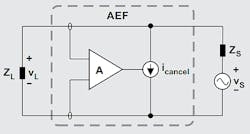
EMI is quite a formidable challenge for power-system designers, especially in the automotive industry with the arrival of autonomous and semi-autonomous vehicles. Enter the integrated active EMI filter (AEF).1 This unique filter design has active circuitry for sensing of noise and then injecting a noise cancellation signal that will reduce the EMI (see figure).
The AEF will sense the noise voltage (VL), then amplify the noise voltage and inject a cancellation current (Icancel) into the system.
As an added bonus, when comparing an AEF vs. passive filter, the AEF will be smaller in size by approximately 50% and lower in volume by 75%, for the same attenuation.
Finally, the AEF is a lower-cost solution than a passive filter design because the AEF doesn’t use large inductors and capacitors in the design architecture.
Adding the EMI Filter to Your Design
Now we need to integrate the EMI filter properly in the overall design architecture. Important points to keep in mind:
- Take care when bundling cables. Don’t combine the load end and power cable end together.
- Keep power lines as short as possible.
Conclusion
To summarize, designers will need to choose their filter type and design architecture depending on local EMI regulations, electrical specifications that the designer must meet for best performance in the particular system. Many other system design requirements may depend on the system architecture, such as filter location, cooling, physical size, heatsinking, shielding, etc.
In most cases, a standard off-the-shelf filter can meet an application’s requirements. However, in certain designs, a custom EMI filter solution becomes necessary to meet the application-specific parameters.
Read more articles in the TechXchange: Delving into EMI, EMC and Noise
References
1. Active EMI filters to reduce size and cost of EMI filters in automotive systems, 2021
2. PCB Design Guidelines For Reduced EMI
3. The Importance of EMI Shielding in Medical Devices - SAT Plating
4. FDA/CDRH Recommendations for EMC/EMI in Healthcare Facilities | FDA
5. EMI filter components and their nonidealities for automotive DC/DC regulators

