Field-Oriented Control Helps Create Tomorrow’s Cordless Power Tools
Download this article in PDF format.
If you’ve browsed the aisles in your local building-supply store recently, you’ve no doubt noticed some big changes in the power-tool and garden-appliance sections. Such products range from drills, sanders, and circular saws to lawnmowers and edge-trimmers to vacuum cleaners.
First came the move to cordless devices powered by batteries. Later generations of power tools added more sophisticated electronic controls, beginning with full-bridge drivers for brushed motors, then a change to more-efficient brushless dc (BLDC) motors. These allowed for longer battery life but required a more complex control scheme with sensors, half-bridge power drivers, and a controller to manage the switching sequence.
The latest power tools are even including wireless connectivity via Bluetooth Low Energy (BLE). Homeowners can now track down their borrowed tools, and the construction professional can improve their anti-theft and inventory-tracking systems.
Sponsored Resources:
- Interactive, cordless power tool block diagram
- Maximize your power tool design with power blocks
- Get more power density in your next generation power tool design
A Cordless Power Tool Must Satisfy Multiple Requirements
What’s needed in a state-of-the-art cordless garden tool these days?
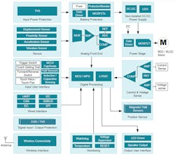
The Cordless Handheld Garden Tool overview page (Fig. 1) from the Texas Instruments website shows some of the available options. Online, each block is a clickable link that brings up relevant reference designs, products, training, and other resources.
1. Browse some of the available features and products by visiting the Cordless Tool Overview Page. (Source: TI Application: Cordless power tool)
The performance of a current-generation cordless power tool is much superior to that of the simple tools of few years ago. As you can see, it includes many more features; we’ve discussed some of these, such as wireless connectivity, in previous articles.
In this article, we’ll look more closely at recent developments at the core of the design: the microcontroller and the motor-control algorithm. Then we’ll examine a reference design from TI that helps the designer incorporate this new technology into his or her power-tool design.
BLDC Operation and Traditional Control Methods
Unlike a brushed motor with its permanent-magnet stator, wound armature, and mechanical commutation, the BLDC stator contains windings that are energized in sequence to create a rotating electromagnetic field. The BLDC rotor then turns as its permanent magnet follows the moving field. The standard BLDC configuration contains six coils arranged into three phases located symmetrically around the motor at 120-degree intervals.
The rotor flux is aligned along the North-South axis of the permanent magnet. If the rotor is perfectly tracking the stator flux with zero phase lag, the motor is generating zero torque—the no-load condition. If a load is then applied to the motor, the motor is generating torque, and the rotor flux will start to lag the stator’s magnetic field. As the torque demand continues to rise, there’ll be an increasing phase lag between the rotor flux and the stator flux. The maximum motor torque for a given current occurs when the phase lag is 90 degrees. If the torque demand continues to increase, then the phase lag will exceed 90 degrees, the motor will lose synchronization, and the control loop will become unstable.
The task of the BLDC control system is to switch the current to the windings sequentially to maintain rotor movement.
Trapezoidal commutation is the simplest approach. The controller switches the active phases every 60 degrees to maintain rotation. The current waveform for each driven winding follows a trapezoidal waveform. This commutation method adds a ripple to the BLDC torque curve because the phase lag between the rotor flux and the stator flux is continuously changing, so trapezoidal commutation has poor low-speed performance.
Sinusoidal control overcomes many of the drawbacks of trapezoidal control by supplying smoothly (sinusoidal) varying currents to the three sets of windings, reducing the torque ripple and providing smooth rotation. However, these time-varying currents are controlled using basic PI regulators, which perform poorly at higher speeds.
We’ve discussed trapezoidal and sinusoidal commutation in greater detail here. A third option, field-oriented control (FOC), was originally considered unsuitable for cost-sensitive applications because it required an expensive position sensor and copious amounts of processing power. In the last few years, Texas Instruments has developed new products and technologies that make FOC a great choice for power tools and garden appliances. Let’s look more closely at this powerful technique.
FOC Offers Unique Benefits for Power-Tool Designs
Compared to other commutation approaches, FOC offers many benefits, including full motor torque capabilities at low speeds, excellent dynamic behavior, higher efficiency across a wide speed range, decoupled control of torque and flux, short-term overload capabilities, and four-quadrant operation.
FOC is a torque-control system: Its goal is to generate maximum torque by keeping the rotor field at a constant phase lag of 90 degrees relative to the stator under varying load conditions.
Simpler control schemes attempt to do the same thing, but they have only six commutation options to work with. In contrast, the FOC algorithm is as a scalpel compared to an ax. It calculates the rotor flux angle thousands of times a second and then modulates the currents in the stator windings to maintain the 90-degree phase difference as the rotor turns.
Traditionally, this has been impractical for many applications. The rotor flux is aligned with the rotor magnet, so a rotor position sensor can measure the flux angle. Simple Hall-effect devices, though, don’t have the required accuracy, and a precision position encoder is too expensive for many applications.
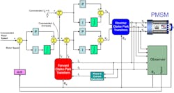
Recently, Texas Instruments has developed a sensorless solution to this problem. Figure 2 shows a block diagram of the sensorless FOC algorithm.
2. The sensorless FOC algorithm eliminates an expensive encoder, but it’s computationally intensive. (Source: TI “InstaSPIN FOC Training” PDF)
The basic procedure for controlling torque is first to measure the currents in the stator windings; compare them with the desired currents by generating an error signal; and then drive the currents to reduce or eliminate the error.
First step: Measure the phase voltages and currents. There are three voltage measurements needed, but only two current measurements. Why? The three phase currents form a closed system. Kirchhoff’s Current Law tells us that ia + ib + ic = 0, so knowing two values gives the value of the third.
A state observer takes the currents and voltages as inputs and calculates both the rotor flux angle θd and the speed of rotation. The speed is compared with the commanded rotor speed, then input to a proportional-integral (PI) controller to generate a commanded current that represents torque.
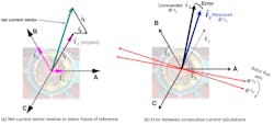
As measured by an analog-to-digital converter (ADC), the three currents are scalar values. But they’re coming from three sets of windings arranged at 120-degree intervals around the stator, so the three currents are actually three vectors with 120-degree phase difference between them. The three phase vectors sum to form a net current vector (Fig. 3a). Each time the FOC samples the currents and calculates the new net current vector, the rotor has moved, generating an error (Fig. 3b) between the old and new values.
3. As the rotor moves, the optimum net current vector (a) changes between successive FOC calculations, generating an error (b). (Source: TI “Intro to Field Oriented Control: InstaSPIN Training,” pp. 5-6)
Remember that the goal of the FOC is to maximize torque by generating a stator flux, represented by the net current vector, that’s orthogonal to the rotor flux. But the phase currents—and, hence, the net current vector—are in a stationary frame of reference, and the rotor flux is, well, rotating. The net current vector must be transformed to the rotor’s rotating frame of reference so that the error can easily be calculated. The rotating frame has its d-axis aligned with the rotor’s flux axis and the q-axis is orthogonal to the flux axis.
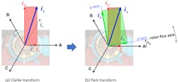
This is done in two stages (Fig. 4). The Clarke transform first converts the three current vectors (ia, ib, ic) into two orthogonal vectors (iα, iβ). Then the Park transform converts those vectors from the fixed to the rotating frame of reference. The result is a current vector is, composed of iq and id. Since iq is orthogonal to the flux axis, it’s the only part that contributes to torque.
4. The forward Clarke-Park transform converts the three phase currents (ia, ib, ic) in the stationary frame of reference to (iq, id) in the rotor’s frame of reference. (Source: TI “Intro to Field Oriented Control: InstaSPIN Training,” pp. 8-9)
The final step is to compare the desired and actual values and use the error signals to generate new phase current outputs. The PI regulator is the standard controller for current, so the FOC block diagram in Fig. 4 contains two PI blocks, one each for iq and id. Since id is along the rotor flux axis and doesn’t contribute to torque production, the commanded id input is set to zero to try and maximize the iq component.
The outputs of both PI outputs are still in the rotating frame of reference, so a reverse Clarke-Park transform converts them back to the stationary frame to supply the power stage and drive the windings.
To learn more, consult Dave Wilson’s excellent section on FOC in the “Teaching Old Motors New Tricks” training series on the TI web site.
In a typical implementation, the FOC runs under interrupt control at 100-µs intervals, so these calculations require considerable computing power.
InstaSPIN Simplifies FOC Development
The FOC method offers excellent performance, but tuning the algorithm for a particular motor still represents a formidable design challenge. InstaSPIN, Texas Instruments’ latest FOC algorithm, makes the job a lot easier. It’s a ready-made set of functional blocks that allows the user to optimize the performance of a wide of variety motors over the full range of operating conditions. There are two versions:
- InstaSPIN-FOC: Torque or velocity control for sensorless applications of three-phase motors
- InstaSPIN-MOTION: Position or velocity motion control for sensored three-phase motors
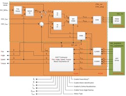
For power tools, InstaSPIN-FOC can identify the motor type, tune the torque controller, and control it in minutes, without the use of any mechanical rotor sensors. The FAST estimator (Flux, Angle, Speed, Torque) is a universal three-phase software encoder that performs the state observer function in Fig. 2. The FAST block can estimate the rotor flux position and provide stable feedback to the control system, without the need for tuning. For more information, consult the InstaSPIN user guide.
As we mentioned, the FOC is computationally demanding. TI has embedded the InstaSPIN FOC software within select C2000 real-time control microcontrollers (MCUs). Depending on the MCU selected, users can run both the FAST estimator firmware and FOC functions purely from ROM or run only the FAST firmware in ROM and the FOC from user memory (RAM or flash).
The TMS320F280040C Piccolo microcontroller, for example, includes the library preloaded in on-chip ROM memory (Fig. 5). Users can directly access the FOC functions as C-callable library routines.
5. Piccolo MCUs with Insta-SPIN contain the FAST estimator in ROM and the FOC control loop (green dotted block) either in ROM or user memory depending on the model. (Source: TI “InstaSPIN-FOC and InstaSPIN-MOTION User’s Guide)
The hardware of the Piccolo MCUs is optimized for real-time control applications. Features of the TMS320F280040C include a 32-bit core running at 100 MHz; a single-precision floating-point unit (FPU); a Viterbi/complex math unit (VCU-I); a trigonometric math unit (TMU) for faster processing of common trigonometric functions; and a comprehensive set of high-performance analog blocks. For FOC implementations, the TMU allows the device to perform a Park transform in 13 clock cycles.
Design Example: 1-kW Power Stage with FOC Interface
Regardless of the means of commutation, the MCU or motor controller can’t supply enough current to energize the stator windings directly, so a complete design requires a power stage.
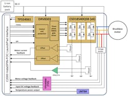
Let’s look at a design example that uses FOC and InstaSPIN in a power tool application. The highly efficient power-stage reference design in Figure 6 can deliver 1 kW from a 10-cell Li-ion battery pack with operating voltage of 30 to 42 V. The complete power stage has a very small form factor of 57 × 59 mm.
6. A 1-kW power stage that’s suitable for a garden or power tool. (Source: TI Designs: “1-kW/36-V Power Stage for Brushless Motor in Battery Powered Garden and Power Tools” PDF)
The core of the design is a pre-driver and three half-bridges. The DRV8303 provides three half-bridge drivers for n-channel MOSFETs and can supply programmable gate current of up 1.7 A (source) and 2.3 A (sink). The part also includes shoot-through prevention circuitry, a full set of protection features, and dual integrated current-shunt amplifiers. An OPA2374 rail-to-rail I/O op amp provides the third current-shunt amplifier.
The reference design uses six discrete NexFET power MOSFETS for the three half-bridges. NexFET is TI’s third-generation macrocell power MOSFET technology. It features similar conduction loss compared to TrenchFET devices, but lower parasitic capacitances for reduced switching loss.
The CSD18540Q5B used here has a drain-to-source resistance (RDS(ON)) of 1.8 mΩ and is offered in a SON 5 × 6 mm package with a very low junction-to-case thermal resistance (RθJC) of 0.8 °C/W maximum.
The reference design includes a LaunchPad interface for a plug-in MCU development board. For this design, the plugin is the LAUNCHXL-F280049C evaluation board for the Piccolo F28004x MCU we discussed above. A companion MotorControl SDK for InstaSPIN-FOC projects will soon be available. Contact your local TI representative for more information.
Three other integrated circuits complete the design. A TPS54061 200-mA synchronous step-down dc-dc converter provides 3.3-V power to the LaunchPad interface. Finally, a TPD4S009 TVS array and an LMT84 temperature sensor add protection and monitoring.
Conclusion
The field-oriented control method has long offered designers a highly-desirable combination of performance features but was considered too expensive for cost-sensitive applications. With the Piccolo microcontroller family of products, the embedded InstaSPIN FOC module, and a reference design demonstrating their use, Texas Instruments has brought FOC capability to the latest generation of power tools.
Sponsored Resources:
About the Author
Paul Pickering
Paul Pickering has over 35 years of engineering and marketing experience, including stints in automotive electronics, precision analog, power semiconductors, flight simulation and robotics. Originally from the North-East of England, he has lived and worked in Europe, the US, and Japan. He has a B.Sc. (Hons) in Physics & Electronics from Royal Holloway College, University of London, and has done graduate work at Tulsa University. In his spare time, he plays and teaches the guitar in the Phoenix, Ariz. area

