Determining Voltage Accuracy of Switch-Mode Power Supplies
What you'll learn:
- The influences and tolerance that impact SMPS voltage accuracy.
- Tools that can be used to optimize a power-converter circuit loop and measure load transients.

Switch-mode power supplies (SMPS) have a feedback pin that can be used to set an output voltage. This voltage is regulated by the power-supply circuit. However, the question arises as to how precisely the voltage is regulated.
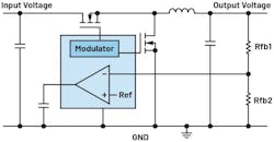
Figure 1 shows an SMPS according to the step-down principle. An existing, usually unregulated, supply voltage (input voltage) is used to generate an output voltage, which is regulated as accurately as possible.
The accuracy of the output voltage is determined by several influences and tolerances.
DC Tolerance
The DC regulation deviation includes the accuracy of the reference voltage contained in the voltage converter (Fig. 1, again). This has been created by the IC designer in such a way that only minor deviations occur within the supply voltage range, the manufacturing tolerances of the IC, and the operating temperature.
The existing tolerance is included in the datasheets of the voltage converter ICs. This value can be specified in different ways: as reference voltage line regulation, as output voltage load regulation, and as regulated feedback voltage. In addition to the accuracy of the pure reference voltage, the latter also includes other IC-specific DC tolerances at the feedback pin.
The DC tolerance also includes the deviation of the resistance values of the resistor divider between the regulated output voltage and the feedback pin (Rfb1 and Rfb2 in Figure 1). These resistors can be purchased with different tolerance ranges.
>>Download the PDF of this article, and check out the TechXchange for similar articles and videos


Usually, a resistor has a resistance value close to the maximum specified tolerance. Better resistors, with a smaller tolerance, are detected during manufacturing of these resistors and are typically sold as more accurate resistors.
Output Voltage Ripple
The regulated output voltage always has a certain voltage ripple in a switch-mode power supply. This ripple is determined by the rise and fall of the inductor current of a buck regulator and the value of the output capacitor and its equivalent series resistance (ESR).
The voltage ripple can be reduced by a high inductance value of the coil and a large output capacitor with a low ESR. However, the output voltage ripple can’t be completely prevented in an SMPS.
Load Transients
The third influence on the accuracy of the generated voltage is its behavior during load transients. If the load current changes, the voltage generated may deviate upward or downward. The higher the amplitude of the load transient and the faster it occurs, the greater the short-term deviation of the output voltage from the set point.
To keep this influence on the error of the generated voltage as low as possible, the control loop speed must be fast. One tool that can optimize a power-converter circuit loop is LTpowerCAD from Analog Devices.
Figure 2 shows the load transient of the LT8642S. The load current is increased from 100 mA to 5 A within 500 ns and scorched again after 250 µs. The voltage peak is about 27.5 mV and the voltage dip is approximately 26.4 mV.
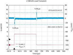
Measurement of the load transients was carried out with ADI’s LTpowerAnalyzer. With this hardware, load transients can be measured easily for different current levels and with different transition times.
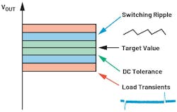
Figure 3 shows the different available influences on the tolerance of an SMPS.
Conclusion
When selecting a power-supply circuit, it’s essential to determine what voltage accuracy is required in an application. This is necessary to select the different components, such as the power-converter IC and resistor divider for DC accuracy, as well as the coil and output capacitor for the output voltage ripple and the load transient influences.
The control loop of the circuit is optimized to handle load transients as well as possible; for example, with the lowest possible voltage offset.
>>Download the PDF of this article, and check out the TechXchange for similar articles and videos
About the Author

Frederik Dostal
Power-Management Technical Expert
Frederik Dostal is a power-management expert with more than 20 years of experience in this industry. After his studies of microelectronics at the University of Erlangen, Germany, he joined National Semiconductor in 2001, where he worked as a field applications engineer, gaining a lot of experience in implementing power-management solutions in customer projects. During his time at National, he also spent four years in Phoenix, Arizona (USA), working on switch-mode power supplies as an applications engineer.
In 2009, he joined Analog Devices, where since then he held a variety of positions working for the product line and European technical support, and currently brings in his broad design and application knowledge as a power-management expert. Frederik works in the ADI office in Munich, Germany.
Also check out my:
Comment About the Article
To join the conversation, and become an exclusive member of Electronic Design, create an account today!

Leaders relevant to this article: