How to Use a Multiphase Boost Converter
What you'll learn:
- Benefits of using a multiphase boost converter to achieve higher voltages.
- Designing a multiphase boost converter.
- Example of implementing such a converter in an IC.
Switch-mode power supplies (SMPS) based on the boost principle can convert a low voltage into a higher voltage. For this purpose, the standard boost topology is used as shown in Figure 1.
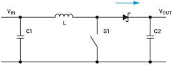
This topology ensures that the output side receives pulsed currents from the inductor. However, since a voltage converter requires a fixed output voltage, output capacitor C2 has an important task. The capacitor must average the pulsed currents into a fixed output voltage.
To perform this task successfully, output capacitors in boost regulators typically must be quite large by having, for example, high capacitance values. They must also have the lowest possible equivalent series resistance (ESR), parasitic resistance, and low equivalent series inductance (ESL), parasitic inductance.
>>Download the PDF of this article, and check out this TechXchange for similarly themed articles and videos
Designing a Multiphase Boost Converter
To reduce this high demand on the output capacitor, it’s advisable to design a multiphase boost converter. In this case, two boost regulators work in parallel and are connected to the same output capacitor. The two channels are controlled with a time lag of 180°. The circuit diagram is shown in Figure 2.
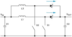
Here, output capacitor C2 receives energy twice in one cycle, once from L1 and once from L2. To obtain a voltage ripple like that of the circuit in Figure 1, only about half the C2 capacitor size is required.
Multiphase boost regulators have advantages not only in terms of output capacitors, but also in relation to input capacitors. On the input side, a boost regulator doesn’t have pulsed currents, as the inductance limits the current increase and decrease. However, two phase-shifted coils, as shown in Figure 2, can also limit the input current fluctuation. This allows the input capacitor C1 to be reduced in size as well.
A multiphase boost converter also increases the conversion efficiency. By dividing the power over several paths, the peak currents per component decrease, thus increasing efficiency.
Two-Phase Boost Converter
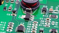
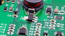
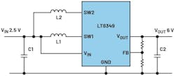
Figure 3 shows a practical implementation with an integrated circuit, an LT8349. This two-phase synchronous boost converter maintains a voltage range that’s designed to increase or stabilize battery voltage. If a higher current is drawn from batteries for a short time, the battery voltage drops temporarily. A two-phase boost converter is ideal for such operation. Due to the phase-shifted behavior, a current with a higher continuity is taken from the battery.
Another special feature of the solution with an LT8349 is its ability to achieve very high efficiency even at low load currents. To be exceptionally efficient in this mode of operation, one of the two phases can be switched off at low loads.
At low load currents, the battery isn’t particularly stressed anyway, and the circuit works with one phase. If higher load currents of several amps are required, the second phase switches on automatically and offers all of the advantages of two-phase operation. This shutdown of a phase in low load operation is referred to as phase shedding.
The example circuit in Figure 3 converts 2.5-V supply voltage to 6-V output voltage. A 3-A load current achieves an efficiency of 92%. With a load current of only 2 mA, an efficiency of 90% can be measured.
Conclusion
There are distinctive ways to operate a boost converter. Two-phase operation offers advantages in terms of efficiency for both high and low load currents. A specially adapted integrated circuit makes this unique operation very easy.
>>Download the PDF of this article, and check out this TechXchange for similarly themed articles and videos
About the Author

Frederik Dostal
Power-Management Technical Expert
Frederik Dostal is a power-management expert with more than 20 years of experience in this industry. After his studies of microelectronics at the University of Erlangen, Germany, he joined National Semiconductor in 2001, where he worked as a field applications engineer, gaining a lot of experience in implementing power-management solutions in customer projects. During his time at National, he also spent four years in Phoenix, Arizona (USA), working on switch-mode power supplies as an applications engineer.
In 2009, he joined Analog Devices, where since then he held a variety of positions working for the product line and European technical support, and currently brings in his broad design and application knowledge as a power-management expert. Frederik works in the ADI office in Munich, Germany.
Also check out my:
Comment About the Article
To join the conversation, and become an exclusive member of Electronic Design, create an account today!

Leaders relevant to this article: