Members can download this article in PDF format.
What you’ll learn:
- How to create a wide range of complex signals using simple, cheap microcontrollers.
- A simple process for generating complex signals utilizing standard software tools.
Often during product development, complex test signals are needed beyond those available from common signal or function generators. To meet this requirement, arbitrary signal generators (ARBs) consisting of a fast memory coupled to a digital-to-analog converter (DAC) were developed.
ARBs come in many shapes and sizes dependent on the sample rate, number of channels, and digital resolution. For some applications, one or two analog outputs are sufficient, but occasionally a combination of synchronized analog and digital outputs are required. One such application is driving contemporary high-efficiency radio-frequency (RF) power amplifiers (PAs) or transmitters with 4G Long Term Evolution (LTE) signals.
In this example, two analog outputs are required to drive the in-phase (I) and quadrature (Q) inputs of an RF modulator and several digital outputs for switching sections of the transmitter. A recent prototype digital PA needed just such an ARB.1 For that, a platform using an Arduino Mega2560 was developed.
The Arduino Mega2560 is based around the ATmega2560 8-bit, 16-MHz microcontroller. It has a total of 54 general-purpose input/output (GPIO) pins configured into six 8-bit and one 6-bit ports. Data must be called separately from memory for each port. Therefore, new data appears on each port at different times, so they’re unsynchronized.
In the prototype mentioned above,1 this was be overcome with external 74HC373 transparent latches between the Arduino and the DACs and digital outputs. They were all enabled together after each port had been updated. This resulted in a sample rate of 457 ksamples/s. To increase the sample rate, a new ARB has been developed based on an Arduino Due, offering up to 8.4 Msamples/s.
Hardware Description
The Arduino Due, based on the 32-bit ATSAM3X8E, allows multiple 8-bit DACs and digital outputs to be mapped onto a single port. This ensuring all outputs are synchronized. Sample rate is dramatically improved as only one lookup-table (LUT) call is made from memory. The Arduino Due also runs at a higher clock rate of 84 MHz.
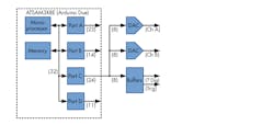
Although 32-bit, none of the four ports (A to D) available on the ATSAM3X8E’s pins map to all 32 bits. Of the four ports, C with 24 bits available is the most useful. A simplified schematic is shown in Figure 1. Along with the digital outputs, a trigger output also is included.
DAC Requirements
The ATSAM3X8E includes internal DACs. However, writing to them takes many clock cycles, resulting in a low sample rate. For this reason, external DAC0801s are used. Although these are quite old, they’re still available and easy to interface. Their datasheet quotes a settling time of 100 ns, consisting of the DAC slewing time and accounting for any ringing at the output to settle.2 The slewing time is a factor of the DAC output current and its load impedance. The DAC0801 has complementary current sink outputs (pins 2 and 4).
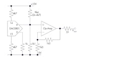
The datasheet for the DAC0801 suggests op-amp active current to voltage (I/V) converters as an output stage. This was found to introduce excess ringing, so passive I/V converters were used instead. With a 1-kΩ resistive load (RL), the slew rate was 30 V/μs, equivalent to a rise and fall time of 42 ns. The schematic of the DAC and op-amp interface is shown in Figure 2.
The peak output current of the DAC0801 is set at 2.13 mA by the 4k7 (4.7k) resistors on pins 14 and 15 when a ±10-V power supply is used. A 1k1 (1.1k) resistor tied to 0 V and two 4k7 resistors in series (9k4, or 9.4k) to +10-V positive supply rail add an offset so that the output voltage at pin 4 swings positive and negative around 0 V. This is a high impedance port, so an op amp with a gain of 2 V/V buffers the output to drive 2 V p-p into a 50-Ω load.
In the prototype, a TL071 proved optimal in terms of bandwidth and ringing. The TL071 has a unity-gain bandwidth product of 3 MHz, reduced to 1.5 MHz with a gain of 2 V/V. Other op amps may provide a better combination of bandwidth, slew rate, and output current.
Programming
Arduinos are very easy to program in C with their free integrated development environment (IDE). The Arduino Due does however use some different commands to those of the more common varieties when directly accessing ports. The following commands setup port C of the Due for direct access:
PIOC→PIO_PER
and
PIOC→PIO_OER
PIOC→PIO_ODSR is then used to write data to the port as shown in the code listing in Figure 3 (see below).
There are a number of “eccentricities” in this code. First, the loop that accesses the LUT and sends it to Port C runs in the setup, not in the main loop. For some reason it ran quicker, taking only 10 instructions and resulting in 8.4-Msample/s output rate.
The LUT allocations are accessed by the variable count, which is a 32-bit integer. This is masked (by ANDing) with FF (256) in the example shown here. Increasing this to FFF would allow for the addressing of a 4096 allocation LUT, etc. Restricting the LUT to powers of 2 simplifies (and hence speeds up) the code. For other values, an IF or FOR loop could be used to reset count at any value.
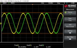
The code listed in Figure 3 generates two quadrature sine waves on the two DAC outputs (Ch A and Ch B) at 32.8125 kHz (8.4 Msamples/s / 256). count is incremented by 1 on each iteration. Increasing the increment value would increase the sine-wave frequency similar to direct digital synthesis.3
Another eccentricity of the code is including the noInterrupts command to disable interrupts even though none were set. If not included, the compiler appears to enable an interrupt by default, resulting in jitter on the output waveform. If a lower sample frequency is desired, though, the delayMicroseconds command can be included. In this case, noInterrupts should be commented out.
Data Generation
The data for all ports and the trigger signal are stored in a single LUT (Portvalues in Fig. 3 below). For Port C, the bits available on the external pins are bits 1-8 for Ch A, bits 12-19 for Ch B, bits 21-26 for the digital interface, and bit 28 as a trigger. These are generated individually and then mapped into a 32-bit word by multiplying the individual values by an offset and adding them together, for example:
Word32 = 228*Trigger + 221*Digital + 212*DAC2 + 21*DAC1
The data can be generated in a spreadsheet like Excel or OpenOffice, or programming language like Python or MATLAB. If using a spreadsheet, one useful tip is the “&” function to combine the values of individual cells into a single cell of comma separated values that can be copied and pasted into the Arduino code. LUTs are normally displayed as a square array, i.e., 16 columns by 16 rows for 256 values (like in Fig. 3), instead of a single column.
Figure 3
int count = 0;

//Quadrature Sinewaves, but with the flip over for the incorrect DAC wiring
int Portvalues[256] = { 3389017602, 389017986, 391114946, 391115042, 390590562,
390590946, 392687762, 392950098, 392949810, 392425906, 393081074, 394653834,
394654026, 394916298, 394391722, 394719594,  394981402, 396554650, 397209818,
396947770, 396423290, 396849402, 397111558, 397242438, 396718278, 396456230,
396784038, 396521702, 396652566, 398487958, 398963030, 398701014,  398831798,
399421558, 399159542, 399290382, 396406926, 396832846, 397226190, 396963886,
396767406, 396505518, 396898670, 396873966, 396611614, 397005086, 396808606,
397201502,  394318174, 395006174, 394612798, 395202878, 394940606, 394547390,
392663486, 393056382, 392270206, 392860030, 392466686, 391057662, 390271230,
390664702, 390468094, 388764158,  387977726, 388227582, 386523646, 386327038,
386719998, 385933566, 384524542, 384131454, 384721278, 381837438, 382230974,
380346558, 379953342, 379691326, 378183742, 377790686,  376381790, 375595102,
375988638, 373694750, 374087710, 371728622, 371704174, 370000302, 369737902,
369541166, 367182030, 367575118, 365904014, 365117454, 363151606, 362889334,
361382070, 361513430, 359154006, 359629206, 357269526, 357400806, 355041702,
353272102, 353009862, 350388294, 350519558, 348684538, 349110394, 346489146,
344129754, 344785306,  342163482, 342425962, 340656298, 338035146, 338297162,
336199818, 335675634, 334234034, 331612210, 331612498, 329777298, 329777634,
327680098, 325058850, 325058754, 322961794,  54525954, 52428924, 50331964,
50331868, 48759196, 46661660, 46661996, 44302508, 44302796, 42729548, 39977228,
40501620, 38404276, 38142004, 36569428, 34144404,  33882596, 32309348, 31654180,
29819076, 30343556, 27820292, 27558136, 25330104, 25854264, 26116312, 25788504,
23953688, 23822824, 24084584, 23609512, 23871528,  21643592, 23150984, 23413000,
23282160, 24068464, 23642544, 25346352, 25608656, 25805136, 26067024, 27771024,
27795728, 30155232, 29761760, 32055392, 31662496,  34545824, 33857824, 36348352,
37855424, 38117696, 40608064, 40394816, 42099072, 44982400, 44392576, 46883072,
46194944, 49078528, 50782208, 50978816, 52682752,  54530048, 55316480, 57020416,
57217024, 58921216, 61804800, 61116672, 63606912, 63017088, 65900928, 67604544,
67391808, 69882176, 70144192, 71651776, 74141984,  73453728, 76337568, 75944032,
78237920, 79942112, 80204048, 82325648, 81932368, 84291920, 84488656, 86847792,
88551856, 88125808, 91009520, 90878216, 93237640,  92647752, 94613544, 94875816,
96497768, 96760296, 98726168, 98988120, 100757720, 101019960, 101544376,
103510264, 103248132, 104919428, 105443524, 107802916, 107147364,  107672036,
109506708, 109179220, 111800372, 111538356, 111538548, 114159884, 113504332,
116126156, 116125868, 115863916, 117960732, 117961116, 118485212, 118485308,
120582268  };

void setup() {
  // put your setup code here, to run once:
  noInterrupts(); // Always a good idea to include even if interrupts are not used
  PIOC->PIO_PER = 0x17EFF1FE; // Configure PORTC to PIO controller
  PIOC->PIO_OER = 0x17EFF1FE; // Enable PORTC to output ....
  //bits 1-8 for I, bits 12-19 for Q, bits 21-26 for digital and bit 28 for trigger, b00010111111011111111000111111110
  //Portvalues are (2^28)*Trig + (2^21)*Dig + (2^12)*Q + 2*I can be calculated in Excel or other software.

  start:
  // put your main code here, to run repeatedly:
  count = count + 1;
  //delayMicroseconds(1); // to slow things down, if used, comment out the noInterupts above
  count = count & 0x000000FF; // set to the maximum value of LUT up to 256kB Arduino Due in 2^N
  PIOC->PIO_ODSR = Portvalues[count];
  goto start;

}

void loop() {
  // Works faster if the main loop is in the setup for some reason
}
For example, the “&” command can be used as such:
=Y2&", "&Y3&", "&Y4&", "&Y5&", "&Y6&", "&Y7&", "&Y8&", "&Y9&", "&Y10&", "&Y11&", "&Y12&", "&Y13&", "&Y14&", "&Y15&", "&Y16&", "&Y17&", "
This groups together the values from cells Y2 to Y17 into a single cell so that when pasted into the Arduino IDE, they appear as a single row of 16 columns.
Results
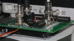
To verify the concept, an Arduino Due “shield” was produced. This was fabricated on standard FR4 substrate using through-hole DIL components. DIL components incur stray inductance and capacitance when operating in the MHz region, but they make it possible to easily modify the design. A surface-mount implementation would probably produce better results than those presented here.
A screen capture of the two quadrature outputs generated by the code in Figure 3 is shown in Figure 4. There’s no output lowpass filter after the DACs other than the frequency response of the TL071. Additional passive filtering would reduce the output switching noise.
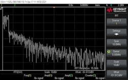
More complex waveforms than sinusoid waves also can be generated—for example, the baseband complex data for a 1.4-MHz LTE signal consisting of 16,384 32-bit words (64 kB). This signal was processed in Python into an array of 1,024 rows and 16 comma separated columns.
The 1.4-MHz LTE signal has a 7.68-Msample/s rate. An additional instruction was included in the Arduino loop, resulting in 11 instructions and a 7.64-Msample/s rate. Further, count was ANDed with 4FFF. The frequency domain of the in-phase (I) baseband signal is depicted in Figure 5.
The 1.4-MHz LTE signal includes guard channels, resulting in an actual RF bandwidth of 1.08 MHz (consisting of six 180-kHz resource blocks). The baseband bandwidth is half of this—504 kHz—as clearly shown in Figure 5. There’s substantial spectral regrowth in Figure 5, partially due to DAC nonlinearities and spurious products introduced by the system.
Another ARB application is to directly synthesize modulated RF carriers without any upconversion. This is often promoted with very-high-speed (>10 Gsamples/s) ARBs for generating signals with multi-GHz bandwidth at GHz carrier frequencies.4
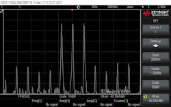
Figure 6 shows a simpler example involving a triple tone test. The three tone frequencies are 984.375 kHz, 1.00078125 MHz, and 1.0171875 MHz.
These three resulting frequencies (Fr) were calculated with:
Fr = Fs * n / LUTs
where Fs is the sampling frequency, n is a whole number to avoid discontinuities—reducing spurious products—and LUTs is the LUT size. Here, Fs was 8.4 Msamples/s; n was 60, 61, and 62; and LUTs was 512. Figure 6 shows the spectrum. Even with all of the harmonically related spurious products, they are −38 dB relative to the three tones. A higher-resolution DAC would offer greater dynamic range, and hence lower spurious products.5
Conclusion
A technique using an Arduino Due to generate arbitrary waveforms with multiple analog and digital outputs is discussed in this article. It’s seen as a starting point for exploration of what’s possible with low-cost, hobbyist-level electronic development boards. Promising results are presented for the generation of sinusoid waves, LTE 4G baseband signals, and three tone tests.
Alternative platforms running at higher clock frequencies like the Arduino Portenta H7, Raspberry Pi RP2040, Raspberry Pi Zero 2 W, or ESP32 could provide higher sampling frequencies and better results. Similarly, so could higher-resolution DACs and better op-amp buffers. The next phase of this research is to combine the LTE signal generator with a low-cost quadrature modulator development board to generate 4G signals for testing transmitter architectures.
References
1. Watkins, Gavin, “A Digital Power Amplifier for 32-QAM,” 51st European Microwave Conference, 2022.
2. Williams, Jim, “30 Nanosecond Settling Time Measurement for a Precision Wideband Amplifier,” Linear Technology Application Note 79, Sep. 1999.
3. Frenzel, Louis E., “DDS Basics,” Electronic Design, June 26th, 2008.
4. Keysight Technologies Inc., “High Speed Arbitrary Waveform Generator,” Microwave Journal, Oct. 24, 2014.
5. McHugh, Brendon, “Evaluating ADC and DAC Performance Characteristics,” Electronic Design, May 25, 2021.
