Flexible Sensors Look for Leaks in Liquid-Cooling Systems
What You'll Learn
- The liquid-cooling technologies trending up and trending down as AI racks become more power-hungry
- Why existing sensors struggle to detect leaks in complex cooling architectures and with newer coolants
- How a new flexible sensor film can detects microscopic leaks before they cause broader failures in data centers

Liquid has long been the enemy of electronics. Yet inside today's AI data centers, coolant is now flowing within inches of some of the most advanced and expensive chips ever made.
As GPUs generate more heat per square centimeter than conventional cooling fans can realistically remove, hyperscalers and other tech giants are rapidly adopting liquid cooling. However, moving millions of gallons of water and other coolants between racks, into servers, and across increasingly delicate electronic assemblies raises new risks. A microscopic leak from a pump, a slow drip from a ruptured hose, or even condensation forming on a manifold can have costly consequences if left undetected.
A coolant leak can lead to anything from a single failed component to an unplanned data-center outage, said Joshua Windmiller, CEO of Serinity, a new startup developing flexible sensors to detect liquid-cooling leaks. The conformal film be placed directly on pipes and other cooling infrastructure and works with precision analog circuitry to continuously monitor for moisture. Beyond data centers, Serinity said the tech could also be adapted for EV-battery thermal management and power transformers.
Electronic Design asked Windmiller to discuss the rise of liquid cooling, the risks of coolant coming into contact with electronics, and where the startup's sensor technology could fit into the data center. This interview has been edited for clarity.
ED: Liquid cooling is becoming much more widespread in data centers. How is the technology itself evolving? Which techniques are trending up, and which ones are trending down?
JW: Three shifts are happening at once: racks are going fully liquid, coolant is getting warmer, and the industry is consolidating around single-phase direct-to-chip (DTC) cooling while it works out what comes next.
Single-phase cold plates are the current standard (Fig. 1). They represent the vast majority of liquid-cooled capacity in a market that hit $3 billion in 2025, heading to $7 billion by 2029, according to Dell’Oro. At the same time, the share of rack heat captured by liquid keeps climbing. Lenovo's GB300 NVL72 guide puts it at roughly 90% liquid and 10% air at a 135 kW TDP, and NVIDIA describes Vera Rubin NVL72 as liquid-cooled down to every chip and networking component, with no fans.
Supply temperatures are rising, too. Vera Rubin is designed for roughly 45°C inlet and 55°C return water, which largely eliminates chillers. Heat rejection is also consolidating into larger CDUs: Google’s Project Deschutes CDU specification is rated to 2 MW.
Coolant chemistry is standardizing, as well. The Open Compute Project (OCP) put out a specification for a single-phase, propylene glycol-based heat transfer fluid designed for both direct-to-chip and cold-plate liquid cooling systems. Separately, some OEMs now recommend using deionized (DI) water, which is a detail that matters a great deal for leak detection.
Trending up next is two-phase direct-to-chip cooling, which requires roughly 1/5 of the coolant flow compared to single-phase cooling for every kilowatt of heat dissipation. As a result of that, two-phase cooling makes a lot of sense as the thermal design power (TDP) ratings of GPUs push past 1.5 kW. Much further out is microfluidics, which is basically on-chip liquid-cooling. Testing it in the lab, Microsoft has reported up to three times the heat removal of cold plates and a 65% reduction in peak temperature rise.
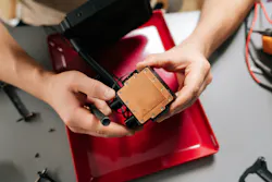
Trending down is two-phase immersion. 3M completed its exit from PFAS manufacturing about a year ago, and the loss of Novec-class fluids has stalled the segment's growth. Rear-door heat exchangers remain useful for retrofitting legacy halls, but practical ratings top out around 70 kW per rack, well below the 130 kW-plus racks now shipping.
How significant is the risk of a leak in a liquid-cooling system? What problems can arise if slow or microscopic leaks aren't detected fast enough?
Individually, the components are very reliable. Collectively, there are a great many of them. An NVL72-class rack carries on the order of 125 to 270 quick-disconnect pairs depending on generation, plus cold plates, manifolds and hoses. A large AI hall holds thousands of racks.
No field leak-rate data has been published for data-center liquid cooling, so we estimate it the way process-safety engineers do. The IOGP and PLOFAM databases put leak frequencies for flanged joints at roughly 5×10⁻⁶ to 1.3×10⁻⁵ per joint-year. Applied to a GB300 rack's connection count, that implies roughly one leak event every two months across a 1,000-rack deployment at the central estimate, albeit there is a wide uncertainty band.
The first-order consequence is downtime, not hardware. A leak caught early is a scheduled isolation of one rack. Caught late, it becomes an unplanned cluster shutdown, and on GB200-class infrastructure the lost compute revenue usually exceeds the cost of losing the hardware.
If a leak progresses to the point where it causes the loss of pressure in the cooling loop, performance can take a hit. We've seen tests of direct-liquid-cooled servers where the CPU throttled its performance within 23 seconds of a total pump failure at full load.
Why is it difficult to detect leaks in liquid-cooling systems? And is it becoming more difficult?
It’s difficult for four reasons, primarily, and two of them are getting worse.
First, most deployed sensing is passive and contact-based. Liquid must physically reach the sensor, in enough volume to register a measurable change. A slow weep at a quick-disconnect can evaporate about as fast as it forms. Slow leaks are often characterized only by residue left behind as the water evaporates. This is a scenario that existing sensors can struggle to catch.
Second, geometry. The highest-risk joints are blind-mate connections inside trays and along manifolds, where sensors can't normally be routed, and residual airflow can carry droplets away from wherever a sensor happens to sit.
Third, signal-to-noise. A leak of a few microliters per minute is invisible in loop flow and pressure data, which move continuously with pump control and valve modulation as well as the thermal expansion of the coolant. This is why slow weeps get buried in the noise and are not addressed until they become more widespread.
Fourth, fluid identity. Conductive sensors only see conductive fluids, yet they also respond to condensation and incidental water, so operators can face both missed detections and false alarms.
Things are getting harder in two ways. First, connection counts are rising: they roughly double from NVIDIA’s GB200 to GB300 as shared cold plates give way to per-device plates. Second, cooling-liquid chemistries are changing: deoionized water is now the recommended coolant in some OEM guides, and conductive cables are unable to detect them. Likewise, newer liquids, such as hydrocarbon and silicon oils, as well as dielectric cooling fluids, exhibit very poor conductivity and will fail to register a change using the incumbent conductometric sensing approaches.
What technologies are used today to detect liquid-cooling leaks, and what are they missing?
There are many different tools in the toolkit today, each one with gaps.
The most widely deployed technology is conductive sensing cable. Two conductors separated by a porous jacket, and the presence of liquid changes the resistance between them. Controllers infer position along the run, typically beneath a bank of racks. It's the incumbent technology, but it requires liquid to pool at the cable, and the liquid itself must be conductive, which is a problem when trying to detect deionized water. Also, hydrocarbon or dielectric fluids require different cables that are incompatible with water.
Spot, or “puck,” sensors operate on the same conductometric principle, but they can only monitor at a single point. They are often paired with drip trays engineered to route liquid to them. Optical sensors can also be used to detect leaks at specific points in the liquid-cooling system. These devices are designed with a prism inside, and when liquid wets the prism, it changes the total internal reflection condition. This approach is fast and fluid-agnostic, but you need to predict where the leak will occur ahead of time.
In many cases, several different technologies are used in the same system. For instance, NVIDIA's GB200/GB300 architecture defines three tiers: tray-level cold-plate and inner-manifold leak sensors read through the BMC, rack-level ropes and spot sensors along piping, and sensors inside the CDU. These sensors can be enhanced by monitoring the coolant loop: flow, pressure and reservoir level in the CDU can be used to catch gross failures. However, early leaks often sit inside normal operating variations.
What's missing across the set is continuous area coverage at microliter sensitivity, independent of fluid chemistry, with the ability to discriminate coolant from condensation. In other words, detection that doesn't depend on anyone guessing where the leak will occur, or waiting for it to pool.
What's different about Serinity's flexible sensor film? How does it work? Where is it deployed?
Serinity's sensor is a printed, flexible film that turns any surface into a continuous detector. Where conventional cable sensing uses a single resistance reading, the solution performs time-domain electrochemical impedance spectroscopy (EIS), resolving each fluid's frequency-dependent permittivity. This spectral signature approach stems from transcutaneous biosensing of pico-ampere electrochemical signals, where our team's work began.
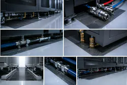
Because it's printed in roll-to-roll form on a thin, flexible substrate, the film can be cut to the desired size and conform to tray floors, manifold runs, CDU bases, and underfloor zones and doesn’t require the drip pans and channels used to bring the leak to other sensors. As a result, the sensor can detect under 5 µL of fluid in under one second, and it works across water-glycol, deionized water, hydrocarbons, and dielectric coolants while distinguishing them from condensation.
Today, we're targeting the protected zones beneath racks, along CDU rows, in piping galleries, and at critical junctures between liquid-handling fittings in data centers (Fig. 2). Our roadmap embeds the film and its nodes directly into rack-level cooling hardware with cooling-system OEMs.
The measurement isn't specific to data centers. The same problem arises anywhere a hazardous fluid runs close to expensive equipment: catching a small leak early and identifying what's leaking. Because the film identifies a fluid by its electrochemical signature rather than by conductivity alone, the same sensor platform could be used, for example, in semiconductor fabs, EV battery-cooling systems, and oil-filled power transformers.
What other components, hardware or software, are part of the solution?
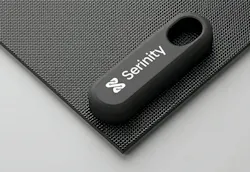
There are three layers to the solution. The film is the sensing element, and then wireless mesh nodes are attached to each film to run the EIS measurement, process the signal locally, and relay alerts (Fig. 3). Delivering sub-second, low-latency detection from a wireless node that runs three to five years on a battery is fundamentally a power-budget problem. The node spends nearly all of its time in deep sleep, waking briefly to measure and transmit status.
Embedded in the battery-operated wireless mesh node is a precision electrochemical analog front-end (AFE) and a low-power microcontroller (MCU) for executing complex pattern-recognition algorithms and data processing routines.
Lastly, software analytics running in the cloud provides an active API for anomaly detection and leak localization, and it integrates with the data-center monitoring systems that companies already use.
What were the biggest technical challenges in accurately detecting these leaks? What influenced the design of the AFE or other parts of the signal chain?
Detecting and "fingerprinting" a few microliters of a poorly-conductive fluid across a large area is fundamentally an electrochemistry problem.
What it requires is a high-precision AFE and electrode array that meet the unique requirements of small-signal electrochemical sensors, and virtually every design decision in the signal chain follows from that. Time domain high-impedance measurements mean that the total amount of charge passing through the detection circuit is vanishingly small, even by even by implantable medical device standards.
The first challenge is measuring high impedance, low margin signals that indicate a liquid-cooling leak. A 5 µL droplet disturbs only a tiny fraction of a large-area sensing surface, so the signal we’re looking for is a small change riding on the channel’s much larger baseline response. Picking it out takes high resolution and very low coupled noise, in an ultra-high-impedance measurement with a narrow integration window.
The front end’s input bias current needs to be in the low picoampere to femtoampere range. Anything larger unduly perturbs a sensor that itself runs at very low current, which adds measurement error and risks false alarms. Getting fast sampling, high resolution, a low noise floor, high input impedance and low power from one signal chain is like squeezing a balloon: press on one requirement and another bulges out. Working with poorly conducting fluids makes this challenge harder still.
The other challenge is that printed conductors are not copper. Printed traces have sheet resistances orders of magnitude above copper, so a long film behaves like a distributed RC line whose response depends on where along it the fluid lands. Unlike copper, the printed conductors do not succumb to corrosion or oxidation and remain robust in challenging environments.
EMI is the other issue. Data centers are electrically hostile. Think high-current busbars and motor-driven pumps in the CDUs. At the same time, measurements are intrinsically high in impedance. The implementation of guarded measurements and driving shields at equal potential to the excitation waveform is one of a number of critical considerations within the design.
What happens after the sensor detects fluid? How do you tell the difference between leaks and noise, condensation, or other false positives?
A threshold alone can't separate coolant from condensation or a cleaning spill. Rather, the molecular composition must be inferred from the unique features of the acquired electrochemical waveform/spectral signature. This requires training of a classification algorithm designed to weigh the features of the waveform against an internal library.
The environment and aging conditions also move the baseline. An embedded calibration routine requires the use of a reference channel and AI/ML models to ensure that the system is stable with time, temperature, humidity, and exposure.
About the Author
 James Morra
Senior Editor
James Morra is the senior editor for Electronic Design, covering the semiconductor industry and new technology trends, with a focus on power electronics and power management. He also reports on the business behind electrical engineering, including the electronics supply chain. He joined Electronic Design in 2015 and is based in Chicago, Illinois.
Joshua Windmiller
CEO, Founder, Serinity
Joshua Windmiller, Ph.D., is the CEO and founder of Serinity. He is a scientist, inventor, and technology entrepreneur with more than 20 years of experience bringing sensing technologies out of the lab and into commercial applications.
With an extensive patent portfolio spanning electrochemical sensors, wearable biosensors, microneedle technologies, and advanced sensing systems, Josh has contributed to numerous patented inventions. His background includes co-founding Biolinq and holding a senior sensing-technology leadership role at Dexcom.
Josh earned his Ph.D. in electrical engineering from the University of California, San Diego, where his research focused on biosensors, bioelectronics, and biofuel cells. His scientific accomplishments include more than 50 peer-reviewed publications, over 100 presentations, and recognition through multiple research and innovation awards. At Serinity, he is applying his extensive experience in precision sensing to a new challenge: protecting the increasingly complex and valuable infrastructure supporting the global AI buildout.
Related
 cooledgraphicscard_dreamstime_181482776
 dreamstime_wateralexandrhlopotov_213763158
Comment About the Article
To join the conversation, and become an exclusive member of Electronic Design, create an account today!
 Leaders Logo
Leaders relevant to this article: