Amping Up the Isolation in Current-Sense Amplifiers
What you’ll learn:
- How a new isolation amplifier is optimized for low-voltage current-sensing applications.
- The method used to achieve isolation, and how the two available isolation ratings are characterized.
- Details of layout and other design-in considerations.
The galvanic isolation of analog signals is often desirable and occasionally necessary or mandated by regulations. Robust isolation can be used to maintain signal integrity, provide user safety, or both.
Some isolation circuits must handle a wide range of voltage signals. Others are optimized for the relatively low millivolt span across the current-sense resistors packed into server power-supply units (PSUs) and industrial motor drives.
That’s the situation for the AMC0x02D precision isolated amplifiers from Texas Instruments, featuring both differential input (±50-mV input) and output. The input is optimized for direct connection to shunt resistors or other low-impedance signal sources. Current-sense resistors are placed in series with a circuit to measure the current flow. By measuring the small voltage drop that occurs as current rushes through it and applying Ohm's Law, the current can be determined.
Current-sense amplifiers are used to accurately measure current by amplifying the tiny voltage output by the shunt resistor, typically in the 10- to 100-mV range. They’re used to enable real-time, closed-loop control for motors, power management, and battery monitoring while improving safety and efficiency.
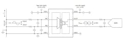
To handle the high voltages and noise prevalent in these systems, TI said the isolation barrier in the AMC0x02D separates the parts of the system that operate on different common-mode voltage levels (Fig. 1).
TI is rolling out two devices with identical specifications, except for the isolation rating and package size. The AMC0202D offers isolation up to 3 kV RMS in a 4.9- × 6-mm package, while the AMC0302D offers more robust, reinforced isolation of up to 5 kV RMS in a 5.85- × 11.5-mm form factor.
The isolation barrier is highly resistant to magnetic interference, which can cause complications in many of its real-world applications. These include industrial-grade inverters and motors, server PSUs, and power factor correction (PFC).
Reliability, Ruggedness, and Robustness: Critical Traits for Isolated Current-Sense Amps
The DC specifications are always of interest in low-level signal-chain analysis and error budgeting. For the AMC0x02D, these errors are quite low. The maximum offset error is only ±50 μV. Other maximum ratings include an offset drift of ±0.9 μV/°C, gain error of ±0.2%, gain drift of ±45 ppm/°C, and nonlinearity of 0.04%.
The device’s supply voltage range is 3.0 to 5.5 V for both the input (high side) and output (low side). It’s fully specified over the extended industrial temperature range of –40 to +125°C.
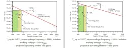
The iso-amps meet key safety-related certifications, including DIN EN IEC 60747-17 (VDE 0884-17) and UL1577 as well as EMI emission standards of CISPR-11 and CISPR-25. As isolation qualifications are tightly defined by VDE and other organization standards, TI also provides isolation capacitor lifetime projections for both the standard and reinforced iso-amps. These projections are rarely available — or even necessary — for non-qualified or non-isolated amplifiers (Fig. 2).
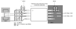
The layout requires the critical placement of the decoupling capacitors and other components needed for the device (Fig. 3). TI also gives engineers guidance on the specific components that can be used to round out the circuit, as well as offers a schematic of a typical current-sensor-to-ADC signal chain.
The Capacitive Isolation Barrier Baked into TI’s Current-Sense Amps
Galvanic isolation of low-level analog signals can be implemented using optical, capacitive, magnetic, and RF principles supported by various forms of analog and digital modulation. In these new iso-amps, the SiO2-based capacitive-isolation barrier supports a high level of magnetic field immunity (Fig. 4). This is the same technology at the heart of TI’s opto-emulators, which are designed to improve signal integrity and save power in high-voltage automotive and industrial applications over traditional opto-couplers.
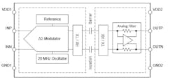
TI said that the input stage of the new iso-amps drives a second-order, delta-sigma (ΔΣ) modulator. The modulator uses on-off keying (OOK) to convert the analog input signal into a digital bitstream. This bitstream is transferred across the isolation barrier that separates the high side from the low side.
On the low side, the received and demodulated bitstream is processed by a fourth-order analog filter that provides a differential output signal that’s proportional to the input signal. The linear input voltage, with a range of ±50 mV, sees a fixed gain of 41 V/V.
The AMC0x02D transmission channel is optimized to achieve a high level of common-mode transient immunity (CMTI) of 150 V/ns, as well as very low levels of radiated emissions caused by the high-frequency carrier and receiver/transmitter buffer switching.
The 46-page datasheet contains all of the detailed specifications that engineers are used to seeing with current-sense amps, including information on thermal derating, thermal drift, and various performance attributes when measured against operating voltage and temperature. Also included are details related to barrier performance under various conditions, which is necessary to ensure the safety mandates can be met. Mechanical, package, and PCB mask details are available, too.
About the Author

Bill Schweber
Contributing Editor
Bill Schweber is an electronics engineer who has written three textbooks on electronic communications systems, as well as hundreds of technical articles, opinion columns, and product features. In past roles, he worked as a technical website manager for multiple topic-specific sites for EE Times, as well as both the Executive Editor and Analog Editor at EDN.
At Analog Devices Inc., Bill was in marketing communications (public relations). As a result, he has been on both sides of the technical PR function, presenting company products, stories, and messages to the media and also as the recipient of these.
Prior to the MarCom role at Analog, Bill was associate editor of their respected technical journal and worked in their product marketing and applications engineering groups. Before those roles, he was at Instron Corp., doing hands-on analog- and power-circuit design and systems integration for materials-testing machine controls.
Bill has an MSEE (Univ. of Mass) and BSEE (Columbia Univ.), is a Registered Professional Engineer, and holds an Advanced Class amateur radio license. He has also planned, written, and presented online courses on a variety of engineering topics, including MOSFET basics, ADC selection, and driving LEDs.