Recently I got a letter from a reader, James Hansen in New Boston, NH. He introduced himself as a digital and analog/digital system design engineer, and said a few nice things about what I write, and then said he had a favor to ask.
I'd like to know how you blue-blooded analog types get those marvelously clear and beautiful low-level waveforms on the scope. I've used everything from crummy scopes through lab-quality scopes, but none of them, regardless of what I've tried, ever produced the squeaky clean displays like the ones I see in the data books.
When I crank up the gain, there's always noise in my displays - usually common-mode noise - that I don't think is really there, but I am not always sure. I'm talking about a lifetime of experience here, in a variety of locations, equipment and breadboards, not just one system that came down the pike yesterday.
I use my very own tried, true, and trusty 465B scope, for which I personally paid Tek some $2600, years ago. In spite of all the TLC I've given this scope, the 50 mV scale is useless if there is anything besides battery-powered flashlights running in the building.
What I find is damped ringing spikes running at either the clock frequency of whatever is under test, or 60 Hz, with the peaks running typically about 3/4 full scale at 50 mV/division, all mixed on top of the real signal. When the gain is backed down to something like 5 V/div, the visual effect is a thick or slightly fuzzy line. This doesn't really bother me much when dealing with large signals, but it is bad news when you need to look at something little.
I've shorted the probes with the shortest ground strap available, and I still see the junk by touching the common ground point - or anywhere else on the chassis. Sometimes I can cut down the amplitude of these dudes a bit with tons of bypassing, but I never come close to eliminating it. I've tried using the scope differentially, I've floated it and/or the test bed, played games with various grounding schemes, and a hundred other things, all to no avail.
So before I die, just once I'd like to hook my scope to the output of a 12-bit DAC and see those uncluttered, beautiful, sharp, clear 5 mV stairsteps like those in the databooks. Is this possible? Do the databook guys cheat, like, touch up the picture?
How does one absolutely, positively know if the junk on the screen is real, or some instrumentation artifact? I've chased this kind of noise for days only to discover (actually, 'proclaim' is a better choice of words) that it wasn't real. Do other people run into this sort of problem, or am I the only soul on earth cursed in such a way?
If you don't care to write the story on this - it would be a boon for humanity - how about giving me some hints, and I'll write it up for publication in the magazine of your choice.
Anyhow, this is the challenge. Will you grasp the ring or beg off? With thanks for your past and future good humor, unknowing help, and encouragement! I am, sincerely yours, James M. Hansen, Project Engineer.
Well, I recognized a guy with a real problem. And it's not just his problem; I'm sure other people have it too. So, remembering the philosophy and the immortal words of LaVerne Baker, "Jim Dandy was the kind of guy, never like to see a pretty girl cry - Jim Dandy to the rescue," I called up Jim Hansen in his lab. I told him I thought I could help him, but this was going to be one of these Onion Syndrome deals - you peel off a couple layers, and cry; then you peel off a couple more layers, and cry some more.
I told him the first thing to do, to get the waveform really quiet, was to put a screwdriver across the master clock in his digital section. He said, after thinking a bit, "Bob, that will cut down the noise a lot, but then I won't be able to get any signal to feed to the DAC, to exercise it." I agreed that was surely true, but if it really did cut down a lot of the noise, that was a good clue. NOW, there may be a little more noise buried behind the local noise, but to a certain extent you do have to clean things up, one after another.
If you try one experiment to cut down the noise, and you can't see any improvement, you may have to do that experiment again later, because it was masked by some other source of noise you cleaned up at an intermediate time. THAT's the Onion Effect at work. But, specifically, I told him, his noise is caused mostly by 3 main problems - a noise source, a transmitting antenna, and a receiving antenna. We can improve all 3 of these.
Let's assume that, as an example, we really do want to add a little 12-bit DAC onto an existing digital system, and we want the analog output to be quiet, and we want to be able to SEE that it is quiet, in real-time - not just by the use of some averaging function on a fancy digital scope.
The first part of the problem is to recognize that the digital system is generating a lot of noise, some of it at more-or-less clock rate, with voltages moving 5 volts in just a few nanoseconds, and other stuff at various rep rates. Example: a low-duty-cycle pulse might drive a couple hundred milliamperes of current into a load, for a few microseconds every millisecond. Even if the current's path does not describe a very big loop (in terms of area), there will definitely be a big amount of magnetic flux coupled into the air. If the circuit was laid out so the current pulses are routed through adjacent parallel busses for Drive and Return, or through twisted pairs of wires, that can help a lot, though.
Now if you have a bus that is nearby the clock or other fast-rise-time signals, you definitely can get capacitive coupling, and even if you have really good bypass capacitors on your power bus, they will also let the current pulses couple magnetically to your signal. So if you put a scope probe anywhere near the computer, the probe can pick up some noises. The electrostatic (voltage-related) part of this noise can be largely eliminated by putting the computer in a sealed metal or copper-clad box. Now you may not want to do that, and you may not be able to, but you may not literally have to do that. Instead, you may be able to just wall the noises out by putting your DAC inside a smaller metal box, so you literally segregate the DAC from the noisy world. The computer's Digital ground and the DAC's Analog ground should be kept completely separate until you link them together at one point - and that point should preferably be right at the DAC. That way, digital noises will not have to flow through the analog ground system, in general, and they will be shielded away from the DAC and the other analog circuits.
Unfortunately copper or aluminum will not reject or attenuate magnetic noises. You might try some iron, but it may take 1/4 in. of steel to do the filtering if you have 60 or 120 Hz noises, and even 1/16 in. is not really guaranteed to shield out high-frequency magnetic flux. When you are really serious, you may have to buy some mu-metal foil or thin sheeting.
What is the realistic thing to do, then? Well, one thing that does cause magnetic coupling to fall off rapidly is distance. You may be able to move the DAC to another board, or another quiet area of your system, farther away from the noisiest digital signals. Or, to be more realistic, if this DAC is going to add into some kind of video display amplifier, you'll want to bring the DAC right over by the load it will drive. That way, after you get the analog signal coming out clean, the signal will be right where you want it. NOW, maybe the DAC has to be driven from a busy computer bus. How can you put the DAC exactly half-way between the busy bus and the pre-amplifier? The answer is, layout. You have to plan and lay it out exactly that way, if that is exactly what you want. For best results, you would indeed have to bring in the digital signals on one side of the DAC, and feed the analog signals directly from the DAC over to its load. But that's still just part of the problem. Let's say you bring your probe over near the DAC, and the scope display is reasonably quiet. But as soon as you touch the probe's ground to the signal ground, horrible noises appear. (This is what I think was Jim's major problem).
There are 3 main aspects of this noise coupling. One, as we have discussed, is to try to get the digital signals to not radiate so much noise; and the SECOND is to try to get less current flowing through the ground path. A majority of scopes have a ground path from their signal grounds, back through the line cord to the ground pin of their power plug. When your scope is plugged in, the ground of the scope is grounded to the building, for safety. But if there is any other source of noise in your building, the noise can couple in through that ground pin. Touching your probe to any other ground enables ground currents to flow through the entire length of the probe, and through the probe's ground wire - a ground loop.
One good thing to do is to use a 3-prong-to-2-prong adapter on the line cord. In some places that might cause trouble or danger, especially if there are high voltages around. But it's worth a try, and this is probably the best way to eliminate 60 Hz ground loops and "ground current." When you do this, hang a fat label on the scope so other users will be warned of this semi-floating condition. Also, be warned that some high-frequency noise currents can still come right in through the power line. Power transformers don't have zero picofarads of capacitive coupling, even the best ones. So a noisy room can still cause large currents to flow as soon as you touch the probe to a signal or ground. In an extreme case, you will have to give up on the line-powered scope, and use a battery-powered scope. Still, even a battery-powered scope can have some picofarads from its case to the world, so you can NEVER cut that current down to ZERO. Still, it's worth an effort to see what improvement you can get by this approach. Then we will go on to the best part of the fix.
The best part is to get the probe's ground wire down to zero length. When you buy a scope, the probes usually come with a 6-inch ground wire, a 12-inch ground wire, and a whole fistful of funny little pieces of metal and plastic that you quickly shove into the back of a drawer and never look at again. WELL, it's just about time to dig them out and look at them. They will be helpful.
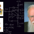
The major problem in this noise test is that the current noises flowing through the scope's ground wire are generating all the large noises, as they flow through the inductance of the ground wire. Shortening that wire is the main solution. Don't just swap the 4-inch ground wire for the 12-inch wire; that's still bad. Instead, unscrew the plastic ferrule or sheath that protects the tip of the probe. (Your probes may need to be disassembled a little differently than mine, but they can all get dismantled in a similar way.) Now you see the metal ground sleeve that is wrapped right around the tip of the probe. Look in the bag of probe accessories and see what kind of small clip is in there, so you can run a 1/4" path from that ground sleeve to the chassis or groundplane of your system (Fig. 1). Slap this small clip securely onto the tip of the probe. (if it falls off into the soup and shorts out and wrecks your circuit, we warned you here .... ) Then connect the tip of that clip to the signal's ground. The noise will be improved by a factor of 20 or 50 compared to what you had before. The main point is, not only is the inductance of the ground strap reduced by a huge factor, but also the coupling of the current into the loop comprised by the probe tip and its ground. That's why probes work so well in the first place.
If you can't find those little probe accessories, you are not in trouble. Form and wrap a piece of bus wire (#20 or 18?) around the ground sleeve of the probe, say, 3 or 4 turns. Then solder that loop to your system ground (Fig. 2). Curl another piece of thin bus around the small wire of the probe tip, about 3 turns, and tack-solder that to your signal. Then you can slide the probe into those sheaths, and let the weight of the probe hold it there. You will have a very short ground path for the price of a penny - and you can fabricate it yourself in just a few seconds, any time you need one!
When I pointed this out to Jim he said, "Why isn't this written down anywhere?" I pointed out that I did mention this in my Troubleshooting book*, on page 15, that if you want to see clean step response with a scope probe, you have to use this VERY SHORT ground path; and that it is also good for minimizing the pickup of noises in the air, too. Maybe I did not emphasize that as much as I should have!
Now, if you called up the applications engineers at Tektronix or any other good scope company, and ask the right question, they would surely be helpful and give the right answer. But you have to know how to ask the right question. Is it written down anywhere? Maybe there are some books on how to use your scope wisely. Not very many.
Now that you have made this major improvement, you will usually want to go back and try all the other experiments, to see which aspects of layout, scope floating, transmitter loops, guarding, shielding etc., will now make the biggest improvement on the observed noise. Because things that made no effect before, can make a difference now.
These inductively-coupled noises will never match exactly if you use 2 probes, so that explains why you could not run the scope preamp differentially to get the noises to cancel. However, John Christensen in our apps group pointed out that you can usually improve this inductively-coupled noise by a couple more octaves, by running a separate, heavy ground wire from the scope to the system ground. If you can get most of the ground current to flow in this path, rather than the probe's ground wire, that's where you can get an advantage. Nick Johnson suggested also that a high-frequency FET probe is usually designed with very short ground paths and will thus be good at rejecting noises, also.
Now, let's say you can look at the ground and it's reasonably quiet. Then you look at the DAC output and it is noisy. There are about five new places to look.
- Does the DAC have a quiet power supply? Many DACs have a PSRR of 70 or 80 dB - at dc. At 5 or 10 MHz, if the PSRR is as good as 6 or 3 or even 1 dB, it's a miracle. Look at the noise on that power supply. Are you feeding a +5-V digital- power bus to your DAC, with 87 mV pk-pk of noise on it? And then complaining because the noise on the output of the DAC looks only a little less bad than the 87 mV? For shame!
- You can try some heavy bypassing. Sometimes a couple 0.1 µF disc capacitors, plus 10 µF of tantalum, plus 220 µF electrolytic, can cut the noise to an acceptable level. (And remember, only YOU can decide what that is ... "good enough" is not necessarily anywhere near "perfection"). If the bypassing alone does not work, then:
- Try some decoupling resistors, perhaps 33 or 120 ohm, or ?? even a ferrite bead, in series with the path of the power from the supply to the DAC. If this is not enough improvement, try:
- A completely separate set of twisted-pair wires from the power supply to the DAC. Put 100 ohm in series with that wire.
- Try a completely separate power supply for the DAC. Repeat all the bypassing. Maybe one or more of these things will solve the problem; maybe none of these will help right now, but they may help later. Remember the Onion Syndrome.
And finally, sometimes the DAC is fed signals from a noisy set of busses that are all-the-time jostling and buzzing, and there is talk-through from these busses into the DAC output. Don't be surprised; there is almost never a spec on that, and this talk-through can be LOUSY. The solution is to make sure the DAC gets its digital signals through a set of drivers or buffers that are running off the same quiet power supplies that the DAC is getting. The bit lines that the DAC sees can get a lot quieter, thus reducing the talk-through effects.
One of the things I like to do is to bring the signal right to the scope. It avoids the 10x attenuation and the possibility of bad phase compensation of the 10x probe; and it avoids the bandwidth limitation of the 1x probe (most of them have barely 10 MHz of bandwidth, and mediocre settling time) and it avoids the capacitance of shielded cable. If you can bring your system to the scope, that has some great advantages, and I recommend it. Maybe you cannot do that. But, it's usually not essential.
What if you do all these things and there is still a little more feedthrough from some systematic noise than you can tolerate? Maybe after you have done all these things, it's time to go back and find out exactly WHAT signal is making the noise, and try to figure out how it is coupling in. Is it a current flowing through a big loop? Maybe that loop can be closed up, or you can use twisted pair or coax cables to get minimum transmitter effect from that signal. Maybe it is capacitive crosstalk from a couple adjacent pc-board runs, and the signals can be shielded or guarded.
This is probably a good time to mention a book by John Barnes, "Electronic System Design: Interference and Noise-Control Techniques."* * It's quite good, practical, and offers several excellent ideas for many kinds of practical problems. He gives a number of good examples throughout. I am delighted to recommend this book; in some respects, it can be considered as a companion to my book on Troubleshooting.
What if you try all these things and there's still some vexing noise, and you turn off the clock and turn off the power supply, and there's still that noise there! Well, that sure gives you a clue, doesn't it? Noises can get conducted into your system by the power supply leads. Maybe you should UNPLUG your power supplies. Certain kinds of noises are brought in by your soldering iron, so, you may unplug THAT, and/or move it several feet away. Transformers for power supplies AND soldering irons can generate a lot of 120/180/360 Hz noise that couples insidiously (magnetically) into an otherwise low-noise system.
And DVMs are often pretty noisy, whether or not they are connected to your signal, so try turning that off. Is there a computer or terminal nearby? Turn that off, too. As you can see, this is rapidly turning into a game of, "Is there anything that cannot be causing that noise?" Maybe that flashlight of Jim Hansen's really is the only item that is unlikely to be the culprit. (And if you shine that on a diode, the light can cause dc currents to flow.) Anyhow, at least we have shown that it probably is NOT the oscilloscope causing all that high-frequency noise, all by itself. It's just a matter of, do you want a good antenna, or do you want a minimum antenna that will reject the noises in the air!
Now, did that help, Jim? Jim says YES. He was enough of a good sport to admit that part of his noise was caused by an oscillator that he had built up several months ago. He had quit using it, but had never disabled or disconnected it from power. He'd forgotten all about it, until these troubleshooting tips led him to the source of the noise. A second source of noise was a transformer whose flux was coupled into a signal fed to a high-gain preamp. The 180 and 360 Hz waveshapes were a dead give-away.
About the Author
Bob Pease
Bob obtained a BSEE from MIT in 1961 and was a staff scientist at National Semiconductor Corp., Santa Clara, CA, for many years. He was a well known and long time contributing editor to Electronic Design.
We also have a number of PDF eBooks by Bob that members can download from the Electronic Design Members Library.
Voice Your Opinion!
To join the conversation, and become an exclusive member of Electronic Design, create an account today!

Leaders relevant to this article: