Backscattered, Harvesting Underwater Acoustic Comms Link Reaches Kilometers
What you’ll learn:
- Challenges in approaches to creating underwater communication links.
- How a unique piezoelectric array can be used for zero-power links.
- The special electrical and mechanical issues addressed when designing and building this array.
It’s well known that underwater communications is a very difficult proposition. Water absorbs a significant fraction of electromagnetic energy and thus attenuates it severely; acoustic energy is also attenuated (though not as severely), though it’s dispersed and distorted.
The low signal levels and low signal-to-noise ratio (SNR) means that establishing a viable underwater link over more than a modest distance—say, around a meter—using a reasonable source power has been a challenge since the earliest days of electronics and electroacoustics.
Underwater Piezo-Acoustic Comms System
Despite these difficulties, researchers at MIT devised a scheme that supports ultra-low-power networking and links at kilometer-scale distances, albeit at modest data rates on the order of 500 bits/s. Applications include monitoring water-based sensors and buoys, aquaculture, coastal storms, and even marine-animal migration patterns.
Unlike many underwater acoustic communication systems, this piezo-acoustic design communicates information via harvesting of backscatter, which is a reflection of external acoustic signals, rather than generating its own carrier. Their design enables backscatter sensor nodes to sense and communicate at five to six orders of magnitude lower power than present-day underwater modems, even at similar data rates.
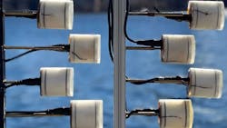
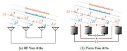
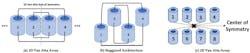
The system uses battery-free piezoelectric-based transducers, which are the standard acoustic source in underwater settings. They then adapted a 70-year-old radio arrangement called a Van Atta array, where symmetric pairs of antennas are connected so that the array reflects energy back in the direction from which it came in a variation of phased-array beamforming (Fig. 1).
This article will focus on the transducers, but briefly look at the link arrangement itself as well.
The Van Atta Cell
An RF Van Atta structure consists of an array of antennas interconnected in symmetrical pairs. This concept was the starting point for the multi-element array, but with major differences due to the nature of the piezo transducer and interconnection. They began with a switching technique known as pass/absorb, where the switches are simultaneously controlled to alternate between these two states to achieve retroreflective backscatter.
However, applying the same idea in underwater backscatter isn’t that simple. Although it’s in some ways similar to an RF phased array and associated beamforming, there are significant differences. First, unlike antennas that typically have one main external feeding point (meaning they are single-ended), piezoelectric transducers are differential. Therefore, they needed a new switch architecture to alternate between different reflective/absorptive states and optimize the backscatter SNR.
Second, in addition to the need for a novel switching architecture, the piezoelectric transducers must be matched to maximize the retroreflective SNR. Unlike antennas that can be easily designed or purchased to have 50- or 75-Ω impedance, it’s very difficult to design a piezoelectric transducer to have a real and consistent impedance. A piezoelectric device is capacitive by nature and even with tight mechanical tolerances, the fabrication of a sealed transducer results in significant process variations in the measured impedance.
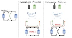
Instead, they used a second switching technique via an arrangement which maintains that the connection between the two nodes be “ON” at all times, but toggles it between in-phase and counter-phase polarities (Fig. 2).
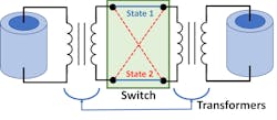
There’s also the issue of impedance matching, as the transducer is highly capacitive and has significant variability. Thus, they needed a mechanism to ensure matching for proper Van Atta operation. To address this problem, they integrated a transformer-based matching network between each node in every pair (Fig. 3).
Having a single Van Atta cell is critical, but it’s only a first step. They had to go from that signal node to a one-dimensional array and then a two-dimensional array. However, doing so brings problems of occlusion and self-blocking.
To achieve retrodirectivity, the elements are connected around an axis of symmetry that’s implemented choosing the inner transducers (nodes 2 and 3) as one pair, and the outer ones (nodes 1 and 4) as the other pair (Fig. 4). Connecting each pair and switching them simultaneously enables retrodirectivity.
Modeling and More
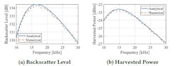
The team developed detailed models of the downlink channel and signal path, as well as the uplink budget, and related this to the transducer and channel parameters. As an example of their attention to detail and fidelity, they first applied the models to spherical-shell piezoelectric transducers. These are the simplest form of underwater transducers, and the only type of underwater transducers with closed-form expressions for all of their acoustic parameters.
However, spherical transducers are omnidirectional regardless of their operating frequency, so this analysis only validated a special case of their analytical expression (Figs. 5 and 6).

Therefore, they extended their analysis to potted cylindrical transducers with a directional radiation pattern that depends on frequency, but doesn’t have closed-form analytical expressions for most of its acoustic parameters at practical backscatter frequencies. To overcome this dilemma, they developed a semi-analytical approach to predict the backscatter performance of practical transducers.
Their overall implementation had three major components: the piezo-acoustic backscatter nodes, fabricated in-house; a transmit-side audio amplifier, also fabricated in-house, which was connected to software radio to generate the downlink signal; and a receiver consisting of an omnidirectional hydrophone with a differential receive-voltage sensitivity of −180 dB (re 1 V/𝜇Pa).
The output of the hydrophone was fed to a four-channel oscilloscope controlled through a LabVIEW code. It recorded the experimental data related to input electrical power as well as the voltage at the backscatter node during downlink power-harvesting verification experiments.
Test and Results of the Underwater Comms System
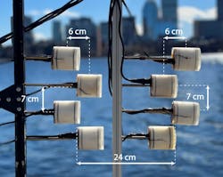
They evaluated their design in a river (4-meter depth) and the Atlantic Ocean (30-meter depth)—most experiments were performed in the river—conducting over 1,500 trials. In the first iteration of the array, they found that if the connected nodes were too close, they would lock out each other’s signals. To overcome this, they devised an improved arrangement where the nodes were staggered (Fig. 7).
These evaluation environments had standard sources of underwater noise and interference, including marine animals, motorboats, sailboats, and ships, as well as other underwater acoustic communication systems. They varied the location, depth, and orientation of the transmitter, receiver, and backscatter nodes.
Experiments were performed across different weather conditions, including wind, rain, and snow. They even built a custom rotating device using a stepper motor and belt drive to rotate a shaft to which the backscatter device was attached, in order to vary the angle of signal path.
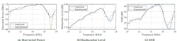
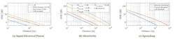
Among the many factors they characterized were link gain (actually, loss); backscatter level from 10 to 18 kHz in steps of 100 Hz (15 kHz provided optimum results); harvested power versus frequency; SNR versus frequency; impact of directivity and spreading loss; and, of course, bit error rate (BER) (Fig. 8).
They compiled a large set of test results with variations in operating parameters and scenarios, using a 4×2 staggered Van Atta array vs. range at 500 bits/s. Applying SNR versus distance for input power of 1 W (blue), 150 W (red), and 2 kW (yellow), they found that the SNR drops below the decodable threshold (6 dB) for 1 W of input power around 20 meters. Upping the power to 150 W increases the decodable range to roughly 60 meters, and it further extends beyond 100 meters with 2 kW of input electrical power (Fig. 9).
As you would expect from a multidisciplinary MIT project, the associated documentation is both thorough and readable. It consists of two detailed papers, one focused primarily on the Van Atta array and transducers (“Enabling Long-Range Underwater Backscatter via Van Atta Acoustic Networks,” 19 pages) and the other of system design (“The Underwater Backscatter Channel: Theory, Link Budget, and Experimental Validation,” 15 pages).
Together, the two documents provide insight and discussion of the underlying problems, equation-laden physics and analysis, review of attempts at solutions and course chosen, detail of modeling of all aspects of the system, description of the final arrangement, references, and test results.
About the Author

Bill Schweber
Contributing Editor
Bill Schweber is an electronics engineer who has written three textbooks on electronic communications systems, as well as hundreds of technical articles, opinion columns, and product features. In past roles, he worked as a technical website manager for multiple topic-specific sites for EE Times, as well as both the Executive Editor and Analog Editor at EDN.
At Analog Devices Inc., Bill was in marketing communications (public relations). As a result, he has been on both sides of the technical PR function, presenting company products, stories, and messages to the media and also as the recipient of these.
Prior to the MarCom role at Analog, Bill was associate editor of their respected technical journal and worked in their product marketing and applications engineering groups. Before those roles, he was at Instron Corp., doing hands-on analog- and power-circuit design and systems integration for materials-testing machine controls.
Bill has an MSEE (Univ. of Mass) and BSEE (Columbia Univ.), is a Registered Professional Engineer, and holds an Advanced Class amateur radio license. He has also planned, written, and presented online courses on a variety of engineering topics, including MOSFET basics, ADC selection, and driving LEDs.
Comment About the Article
To join the conversation, and become an exclusive member of Electronic Design, create an account today!

Leaders relevant to this article: